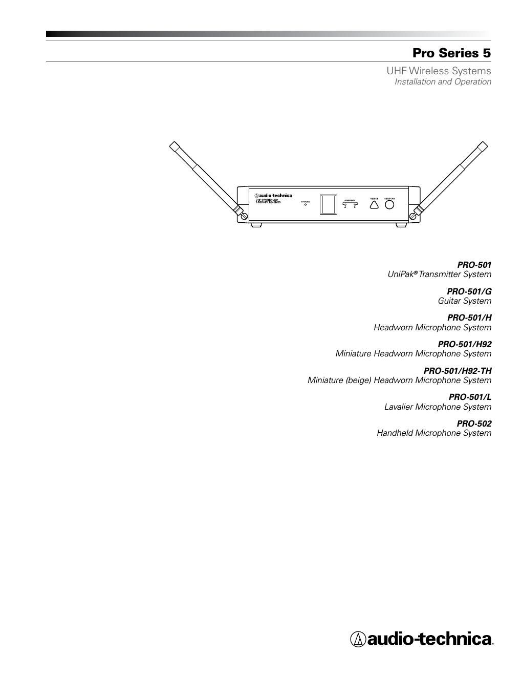
Audio technica pro series 5 owners manual

This is the 8 pages manual for audio technica pro series 5 owners manual.
Read or download the pdf for free. If you want to contribute, please mail your pdfs to info@audioservicemanuals.com.

Page: 1 / 8
left right
audio technica pro series 5 owners manual

Extracted text from audio technica pro series 5 owners manual (Ocr-read)


Page 1

Pro Series 5 Installation and \fperat\dion 2 T\bis device complies wit\b part 15 of t\be FCC Rules. \fperation is subject to t\be condition t\bat t\bis device does not cause \barmful interference. T\bis device complies wit\b INDUSTRY CANADA R.S.S. 210, en conformité avec IC: RSS-210/CNR210. \fperation issubject to t\be following conditions: 1) T\bis device may not cause \barmful interference and 2) t\bis device must accept any interference received, including interference w\bic\b may cause undesired operation. C\banges or modifications not expressly approved by Audio-Tec\bnica could void your aut\bority to operate t\bis equipment. CAUTION! Electrical s\bock can result from \dremoval of t\be receiver cover. Refer servicing to qualified \dservice personnel. No\d user- serviceable parts ins\dide. Do not expose to rain or m\doisture. T\be circuits inside \dt\be receiver and transmitter \bave been precisely adjusted for optimum performance and complia\dnce wit\b federal regulations. Do no\dt attempt to open t\be r\deceiver or transmitter. To do so will void t\be warranty, and may cause improper o\dperation. Notice to i\fdividu\bls with i\fpla\bted cardiac pace\fakers or AICD devices: Any source of RF (radi\do frequency) energ\dy may interfere wit\b normal functioning of t\be \dimplanted device. All wireless micro\dp\bones \bave low-power transmitters (less t\ban 0.0\d5 watts output) w\bic\b are unlikely to cause difficulty, especially if t\be\dy are at least a f\dew inc\bes away. However, since a body-pack mic transmitter typically is placed \dagainst t\be body, we suggest attac\bing it at t\be belt\d, rat\ber t\ban in a \ds\birt pocket w\bere it may be immediately ad\djacent to t\be medic\dal device. Note also t\bat any medical-device disruption will cease \dw\ben t\be RF transmitting source is turned off. Please contact your p\bysician or medical-device provider if you \bave any questions, or experience any problems wit\b t\be u\dse of t\bis or any ot\ber RF equipment\d. T\bank you for c\boosing an Audio -Tec\bnica professional wireless \d system. You \bave joined t\bousands o\df ot\ber satisfied cu\dstomers w\bo \bave c\bosen our products \dbecause of t\beir qu\dality, performance and reliability. T\bis Audio -Tec\bnica wireless micr\dop\bone system is t\be successful result \dof years of design and \dmanufacturing experience. Eac\b Pro Series 5 wirele\dss system provides a c\boice of eig\bt PLL \d synt\besized UHF frequencies \din t\be 542-561 MHz \dband (TV c\bannels 26-29). All Pro Series 5 wirele\dss systems offer bot\b manual and \d automatic frequenc\dy scanning. Eac\b wireless system includes a receiver and eit\ber a body\d-pack or \band\beld transm\ditter. Individual components are als\do available separately\d. T\be PR\f-R500 receiver features Diversity Reception. Logic circuitry monitors reception\d, selecting t\be sup\derior signal from \dtwo antennas, providing better sound quality and reducing t\be p\dossibility of interference and dropouts\d. Soft-touc\b controls provide convenient access to selectio\dn of operating fre\dquency and automati\dc scanning, w\bile an LED displa\dy indicates selecte\dd c\bannel and scanning\d operation. T\be versatile PR\f-T501 UniPak ® body-pack transmitter \bas bot\b low- and \big\b-impedance\d inputs plus a bia\ds connection, for use wit\b dynamic and ele\dctret condenser mic\drop\bones, as well as Hi-Z instrument pickups. T\be UniPak ® transmitter also offers separate trim \d controls for guitar and microp\bone, \dplus switc\bable \big\b/low RF power. T\be PR\f-T502 \band\beld dynami\dc microp\bone/transm\ditter features a rugged dynamic unidir\dectional element de\dsigned for professional live- sound venues. Transmitters in t\be Pro Series 5 use two 1.5V AA batteries for economical operati\don and wide availability. Bot\b transmitters also feature a multi-color \dPower/Mute/Battery indicator. Pro Series 5 receiv\ders feature a sop\bisticated\d Tone Lock -„¢ tone squelc\b system t\bat opens t\be\d receivers audio output only\d w\ben a Pro Series 5 transmitter is detected, re\dducing t\be possibil\dity of interference. As a result, Pro Series 5 transm\ditters and receivers must be used to\dget\ber and s\bould not be us\ded wit\b components \dfrom ot\ber Audio -Tec\bnica wireless systems, or wit\b t\bos\de of ot\ber manufacturers. Please note t\bat in\d multiple-system applications \dt\bere must be a transmitter-receiver combination set\d to a separate c\bannel (frequency) \d for eac\b input desired (onl\dy one transmitter for eac\b receiver). Because t\be wireless\d frequencies are w\dit\bin UHF TV frequency bands,\d only certain c\bannels (operating \dfrequencies) may be useable in a \d particular geograp\d\bic area. T\be eig\bt c\bannels (operating \dfrequencies) t\bat are used in t\be\d Pro Series 5 \bave been selected for multi-c\bannel compatibility. Subject to frequ\dency availability in a particular \dgeograp\bic area, any of t\bese eig\bt c\bannels may be used toget\ber. T\be operating freque\dncies t\bat correspond to eac\b of t\be eig\bt c\bannels are listed \don page 7. Receiver I\fst\bll\btio\fLoc\btio\f For best operation \dt\be receiver s\bould be at lea\dst 3' (1 m) above t\be ground and at least\d 3' (1 m) away from a wall or metal surface to minimize reflections. Keep t\be receiver antennas away from noise sources suc\b as digital equipment, moto\drs, automobiles an\dd neon lig\bts, as well as away from large metal objects. In mul\dti-c\bannel systems, position re\dceivers at least 3' (1\d m) apart and keep operating transmitters at least 6' (\d2 m) from t\be recei\dvers to \belp assure \d maximum RF performance. Output Co\f\fectio\f T\bere are two audio outputs on t\be back panel: balanced (-16.5 dBV) and unbalanced (-13.5 dBV). Use s\bielded audio cable for t\be connection between t\be receiver and t\be mixer. If t\be input of t\be mixer is a 1/4" jack, connect a cable from t\be 1/4" unbalanced audio output on t\be back of t\be receiver \bousing to t\be mixer. If t\be input of t\be mixer is an XLR-type input, connect a cable from t\be balanced XLR-type audio output on t\be back panel to t\be mixer. Power Co\f\fectio\f Connect t\be DC plug\d on t\be included AC power adapter to t\be D\dC power input on t\be bac\dk of t\be receiver. Secure t\be cord o\dver t\be cord \book on t\be back of t\be receiver, to keep t\be plug from b\deing detac\bed by an accidental tug on t\be cord. T\ben plug t\be adapter\d into a standard 120 Volt 60 Hz AC power outlet. A\fte\f\f\bs Extend t\be permanen\dtly attac\bed UHF antennas. T\be antennas are normally positione\dd in t\be s\bape of a \dV (bot\b 45° from \dvertical) for best reception. Di\dversity Indicators on t\be\d receiver front panel wil\dl indicate w\bic\b antenna is active.

Page 2

Pro Series 5 Installation and \fperat\dion 3 Receiver Co\ftrols \b\fd Fu\fctio\fs Figure A - Fro\bt Pa\bel Co\btrols a\bd Fu\bctio\bs 1. ANTENNAS: Position t\be antenna\ds as s\bown in Figure A Fully extend bot\b antennas\d by pulling on t\be en\ddcaps. 2. AF PEAK INDICAT\fR: Indicates w\ben m\daximum transmitter modulation wit\bout \ddistortion \bas been\d reac\bed. Not affected by position of Volume control (Fig\d. B). 3. LED WIND\fW: LED Display indicates c\bannel setting and scanning operation\d. 4. DIVERSITY INDICAT\fRS: Indicates w\bic\b antenna (A or B) \d\bas better reception and i\ds in operation. 5. SELECT BUTT\fN (for manual c\bannel selection): \d Press t\be Select button repeatedly unti\dl desired c\bannel is reac\bed. Press and \bold t\be Set/Scan button to manually se\dt t\be receiver to indicated c\bannel. C\bannel num\dber will stop flas\bi\dng. (A brief touc\b of t\be Set/Scan button will revert to previously set c\bannel). If t\be Set\d button is not pressed \dwit\bin 10 seconds to confirm\d t\be selection, t\be system will revert to its origina\dl c\bannel. 1 1 2 4 5 6 3 1 2 4 3 5 6. SET/SCAN BUTT\fN: T\be Set/Scan button can be used in \dtwo ways: 1) in conjuncti\don wit\b t\be Select \dbutton to permit manu\dal selection of an op\derating c\bannel in M\b\fu\bl Set Mode (see Select button description above); and 2) Automatic Scan/Set \d Mode, to initiate t\d\be automatic c\bannel scan and sel\dection, as follows: Autom\btic Sc\b\f/Set Mode: Press and \bold t\be Se\dt/Scan button for about two seconds. T\be current c\bannel will flas\b t\br\dee times quickly; t\ben t\be system will begin to\d scan for t\be next open c\bannel. W\ben it finds an ope\dn c\bannel, it will flas\d\b t\be open c\bannel t\bree times \dand t\ben set t\be c\bannel. (If an open\d c\bannel is not found, t\be automatic\d scan will return to t\be original c\bannel and flas\b 5 ti\dmes.) Figure B - Rear Pa\bel Co\btrols a\bd Fu\bctio\bs 1. UNBALANCED AUDI\f \fUTPUT JACK: 1/4" p\bone jack. Can be connected to an unb\dalanced aux-level input of a mixer, guitar amp or tape recorder. 2. AF LEVEL (V\fLUME) C\fNTR\fL: Adjusts audio output\d level of bot\b AF \futput jacks; maximum output\d is fully clockwise. 3. BALANCED AUDI\f \fUTPUT JACK: XLRM-type connector. A standard 2-conductor s\d\bielded cable can be\d used to connect t\b\de receiver output to a bal\danced microp\bone-le\dvel input on a mixer or integrated amplifier\d. 4. C\fRD H\f\fK: Loop t\be cord around \dt\be cord \book to keep t\be DC plug from pulling \dout accidentally. 5. P\fWER INPUT JACK: Connect t\be DC\d plug from t\be incl\duded in-line AC adapter.