Arp 2600 service manual

This is the 53 pages manual for arp 2600 service manual.
Read or download the pdf for free. If you want to contribute, please mail your pdfs to info@audioservicemanuals.com.

Page: 1 / 53
left right
arp 2600 service manual

Extracted text from arp 2600 service manual (Ocr-read)


Page 1

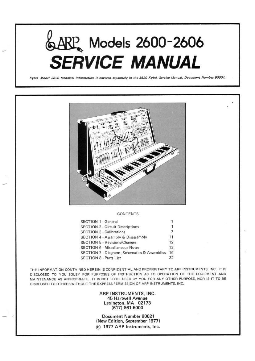
,é Models 2600-2606
SERVICE MANUAL

Kybd. Made] 3620 technical information is covered separately in the 3620 K ybd. Service Manual, Document Number 90004.

CONTENTS
SECTION 1 - General 1
SECTION 2 - Circuit Descriptions 1
SECTION 3 - Calibration: 7
SECTION 4 - Assembly & Disassembly 11
SECTION 5 - Revisions/Changes 12
SECTION 6 - Miscellaneous Notes 13
SECTION 7 - Diagrams, Schematics & Assemblies 16
SECTION 8 . Parts List 32

THE INFORMATION CONTAINED HEREIN IS CONFIDENTIAL AND PROPRIETARY TO ARP INSTRUMENTS, INC. IT IS
DISCLOSED TO YOU SOLEY FOR PURPOSES OF INSTRUCTION AS TO OPERATION OF THE EQUIPMENT AND
MAINTENANCE AS APPROPRIATE. IT IS NOT TO BE USED BY YOU FOR ANV OTHER PURPOSE, NOR IS IT TO BE
DISCLOSED TO OTHERS WITHOUT THE EXPRESS PERMISSION 0F ARP INSTRUMENTS. INC.

ARP INSTRUMENTS, INC.
45 Hartwell Avenue
Lexington, MA 02173
(617) 861-6000

Document Number 90021
(New Edition, September 1977)
© 1977 ARP Instruments, Inc.

Page 2

tuning procedure for the new module and use the oscillators (use the new oscillator as the tuning
4017/4027 tuning procedure for the remaining standard once it hasbeen tuned.)

3.2.5 VOLTS PER OCTAVE ADJUSTMENT PROCEDURE

Ref. No. Trimmer Specifications/Trim Procedure
R60 VCO 1 Monitor VCO 1 output (sawtooth or square) with frequency
V/OCT counter or other tuning standard.
Depress low C and adjust frequency for 100Hz. using coarse and fine
tune sliders.
Depress high C and adjust R60 trimmer (VCO 1V/OCT) for 1600Hz.
Repeat steps 1 and 2 until low and high C are correct.
R78 VCO 2 Repeat same procedure as indicated for V00 1 using V00 2 V/OCT
V/OCT R78 trimmer.
*Note: If VCO 1 V/OCT adjustment has been accurately made then
VCO 2 can be adjusted audibly by comparing its pitch to VCO 1.
R97 VCO 3 Repeat procedure as indicated for VCO 1 and VCO 2 using R97
V/OCT (VCO 3 V/OCT) trimmer.

3.3 Board 1 Adjustments

3.3.1 RING MODULATOR

R33

R34

R35

Positive Null Put audio/d.C. switch to d.c. position.
Raise V00 2 slider into the Ring Modulator onlv.
Monitor Ring Modulator output with oscilloscope and adjust R33
(middle trimmer) for minimum output (should be less than 10mv).
Negative Null Put audio/dc switch to audio position and adjust R34 (lower trimmer)
for minimum output (should be less than 10mv).
Gain Raise both sliders into Ring Modulator and select audio/dc switch to

d.c.

Adjust R35 for 20V P.P, maximum.

3.4 Board 2 Adjustments

3.4.1 VCO 1 PULSE WIDTH ADJUST

R18 -

Pulse Width

Monitor VCO 1 square wave output with an oscilloscope and adjust
R18 for exactly 50% duty cycle (square wave). (Located below VCO 1
Fine Frequency Slider.)