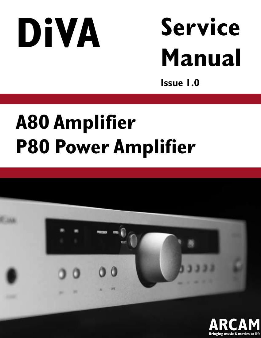
Arcam A80 int sm

This is the 41 pages manual for Arcam A80 int sm.
Read or download the pdf for free. If you want to contribute, please mail your pdfs to info@audioservicemanuals.com.

Page: 1 / 41
left right
Arcam A80 int sm

Extracted text from Arcam A80 int sm (Ocr-read)


Page 1

Contents List ! Circuit description o A80/P80 ! Technical specifications ! Circuit diagrams o L943AY ! Transformers o L916TX -“ 115/230VAC toroidal o L917TX -“ 100VAC toroidal o L907TX -“ 100VAC frame ! Exploded view diagram o A80 ! Mechanical & packing parts list o A80 o P80 ! Circuit board silk screen o A80 o P80 ! Circuit board parts list o A80/P80 combined

Page 2

Circuit description. Power supply. The mains input to the unit is supplied at SK200 and is filtered the Y Caps and locations C200 /C201 and X cap at location C209, these are in-place to reduce mains born HF interference and to prevent bridge rectifier noise from leaving the unit. The mains select switch at location SW200 works in conjunction with the dual primaries on the 115/230v transformers, the switch allows for the units to be used in territories running a 115v or 230v grid when the switch is set to the 115v position the primary windings are connected in parallel. Fig 1. Fuse value information. Fuse location. Value. FS200 T2.5A (20mm) FS201 T2.5A (20mm) FS200 (100v) T3.15A (20mm) FS201 (100v) T3.15A (20mm) FS202 (s.m standby 9v a.c rms) T500mA (s.m) FS203 (D.C inline) T2.0A (20mm) FS204 (D.C inline) T2.0A (20mm) The standby Transformer TX200 continuously powers the digital circuitry (+4.8v(D )) when power is connected to the unit, this supply powers the Micro via a regulating circuit based around regulator REG 201 special mention should be made of fuse FS202 as any interruption to this supply will render the unit completely lifeless and as such this circuit should be checked before inspecting any other areas of the board. We will see that the main power transformer TX200 supplies a separate secondary winding for the +15 and -“15v analogue regulation stages via the two fuses at board locations FS203 and FS204, the failure of either of these fuses will cause the op-amps connected to the regulated rails to swing D.C. The regulator at location REG 200 regulates the +15 rail and intern supplies the +5V(A) analogue supply via the reference Zener at location DZ200 and drive transistor TR200. The high level power amp A.C supplies arrive at Con204 as a 4-wire supply this allows us to implement a dual bridge network circuit with 4 individually smoothed D.C rails these are labelled as +45(L), +45(R) and -45(L), -45(R) we pull a -“38v rail from this point to form the VFD cathode bias voltage via R211 Con205 delivers the 3.3 V A.C supply to the main board and then onto the display VFD via R203 (2R2 f.u). Fig 2. Supply identification and related components. Supply Related components + 45v L Left power amp positive rail. + 45v R Right power amp positive rail. - 45v L Left power amp negative rail. - 45v R Right power amp negative rail. - 38v VFD Display cathode rail derived from -“45v(R) +15v (A) IC 300, 301, 302, 303, 304, 305, 306, 307, 308, 309 also including the input clamp diodes all within the pre-amp stage. - 15v (A) IC 300, 301, 302, 303, 304, 305, 306, 307, 308, 309 also including the input clamp diodes all within the pre-amp stage. + 5v (A) IC309 volume control +4.8 (D) Input trigger stages, signal detect IC700, delayed off IC703, IC701. Main micro IC600.Remote pickup, Master reset IC601, Over current detect-AC detect -“ thermal cut-out IC600 Fil 1/Fil 2 3.3v~ filament supply. Pre-amp. The A80 Pre-amp has inputs for Phono, Aux, CD, Tuner, AV, DVD and Tape. All inputs except Phono have a simple resistor-capacitor 340Khz low pass filter to remove any unwanted high frequency noise from the input signal/local area, a pair of diodes on each input connected to the +15/-15v rails prevent damage to the CMOS input switching chips at locations IC300 and IC301, if any offset is seen at the input the switching chips on a given input we may suspect the failure of one of the input diodes. Fig 3. Logic status of IC302 and 303 (switching chip). Low= 0V High=4.8 (Cmos). Input. A0 (pin 1) A1 (pin 16) A2 (pin 15) Phono Low Low Low Aux Low High Low CD High High Low Tuner Low Low High AV High Low High DVD Low High High Tape High Low Low The outputs of IC300 (L) and IC301(R) can be seen on pin 8 as a current signal and such this can not be viewed via CRO although a 100 ohm resistor inline with the scope probe may yield some results, from here we drive into line drive op-amp IC307 (L) and IC308 (R) signal can be seen at the output pin (1) and travelling into the volume control chip (IC309) on pins 16 (L) and 9 (R) the output from the Volume control is driven into IC307 at pin 6 (L) and IC308 pin 6 (R) and seen again on pins 7 on both IC307 and IC308. After the Con 302 and Con 303 we drive directly