Anatek wind machine operating instructions

This is the 1 pages manual for anatek wind machine operating instructions.
Read or download the pdf for free. If you want to contribute, please mail your pdfs to info@audioservicemanuals.com.

Page: 1 / 1
left
anatek wind machine operating instructions

Extracted text from anatek wind machine operating instructions (Ocr-read)


Page 1

Wind Machine m

OPERATING INSTRUCTIONS

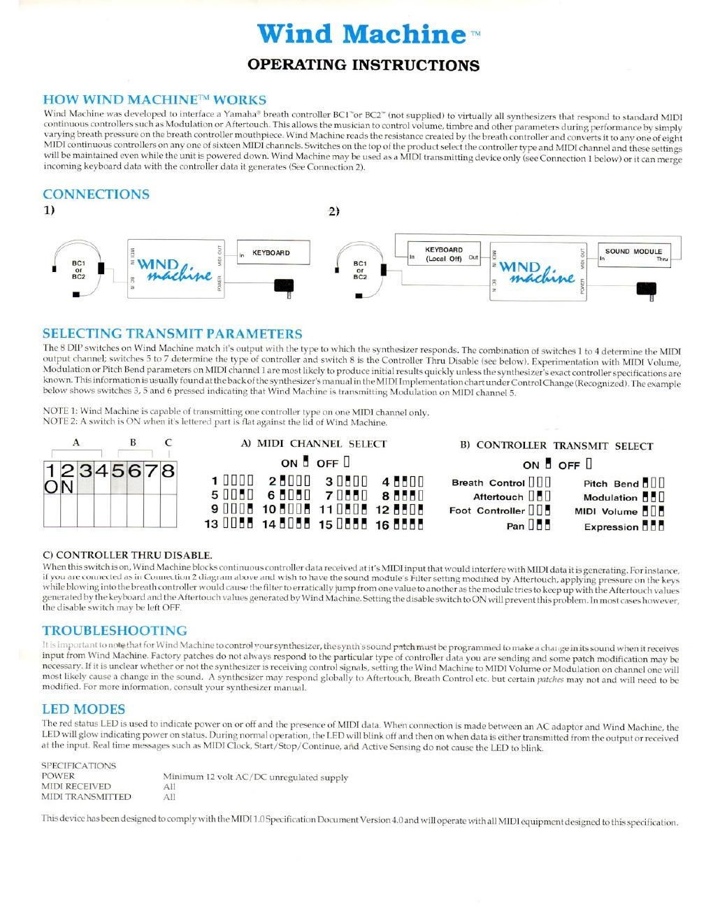
HOW WIND MACHINE"VI WORKS

Wind Machine was developed to interface a Yamaha breath controller BCI"or 8C2 (not supplied) to virtually all synthesizers that respond to standard MIDI
continuous controllers such as Modulation or Attertouchl This allows the musician to control volume, timbre and other parameters during performance by simply
varying breath pressure on the breath controller mouthpiece. Wind Machine reads the resistance created by the breath controller and converts it to any one of eight
MIDI continuous controllers on any one ot sixteen MIDI channels. Switches on the top of the product select the controller type and MIDI channel and these settings
will be maintained even while the unit is powered down. Wind Machine may be used as a MIDI transmitting device only (see Connection 1 below) or it can merge
incoming keyboard data with the controller data it generates (See Connection 2).

CONNECTIONS
1) 2)

t KEYBOARD 7 L KEYBOARD In SOUND MODULIEM J

In l, out
I set E ( turn
or ,
scz

,q . 7 C,

SELECTING TRANSMIT PARAMETERS

The 8 011 switches on Wind Machine match its output with the type to which the synthesizer responds. The combination of switches I to 4 determine the MIDI
output channel; 5 'itches 5 to 7 determine the type of controller and switch 8 is the Controller Thru Disable (see below). Experimentation with MIDI Volume,
Modulation or Pitch Bend parameters on MIDI channel I are most likely to produce initial results quickly unless the synthesizer's exact controller specifications are
known. This information is usually found at the back of thesynthesizers manual in the MIDI Implementation chart under Control Change (Recognized ). The example
below shows switches 3, 5 and 6 pressed indicating that Wind Machine is transmitting Modulation on MIDI channel 5.

NOTE I: Wind Machine is capable of transmitting one controller type on one MIDI channel only.
NOTE 2: A switch is (N when it's lettered part is flat against the lid of Wind Machine.

A is C A) MIDI CHANNEL SELECT B) CONTROLLER TRANSMIT SELECT
l
ONHOFFU ONEOFFU
alfi 345678 1 HEIDI] ZEDDD 3l]fll]l] 4HHUD Bmath Contmlflljl] Pltch Bendflul]
sflflflD GBDHD 7DEHD 855M] Ananouchflfll] Modulationflflfl
QUDUH 10EDUH IIUHDH 12BHDH Foot Contmllerflllfl MIDI Volume HUB
13DDHH 14HUBH 15UHBH 1GHHEH PanIIHB Expressionfiflfl

C) CONTROLLER THRU DISABLE.

When this switch is on, Wind Machine blocks continuous controller data received at it's MIDI input that would interfere with MIDI data it is generating. For instance,
if you are connected as in Connection 2 diagram above and wish to have the sound modules Filter setting modified by Aftertouch. applying pressure on the keys
while blowing into the breath controller would cause the filter to erratically jump from one value to anotheras the module tries to keep up with the Aftertouch values
generated by the keyboard and the Aftertouch values generated by Wind Machine. Setting the disable switch loON will prevent this problem. In most cases however,
the disable switch may be left OFF.

TROUBLESHOOTING

. ,i.., t :tani to notethat t'or \\ind Machine to control "r-ursynthesizer, the synth swund patch must be programmed to inahea change in its sound when it receives
input from Wind Machine, Factory patches do not aim ays respond to the particular type of controller data you are sending and some patch modification may be
necessary. If it is unclear whether or not the synthc r is receiving control signals, setting the Wind Machine to MIDI Volume or Modulation on channel one will
most likely cause a change in the sound. A s th may respond globally to Attertouch, Breath Control etc. but certain pair/us may not and will need to be
modified. For more information, consult your ynlhc-sizer manual.

LED MODES

The red status LED is used to indicate power on or off and the presence of MIDI data. When connection is made between an AC adapter and Wind Machine, the
LED will glow indicating power on status. During normal operation, the LED will blink ofland then on when data is either transmitted from the output or received
at the input. Real time messages such as MIDI Clock, Start/Stop/Continue, and Active Sensing do not cause the LED to blink.

SPECIFICATIONS

POWER Minimum [2 volt AC/DC unregulated supply
MIDI RECEIVED All

MIDI TRANSMITTED All

This device has been designed to comply with the MIDI 1.0 Specification Document Version 4.0 and will operate with all MIDI equipment designed to this specification.