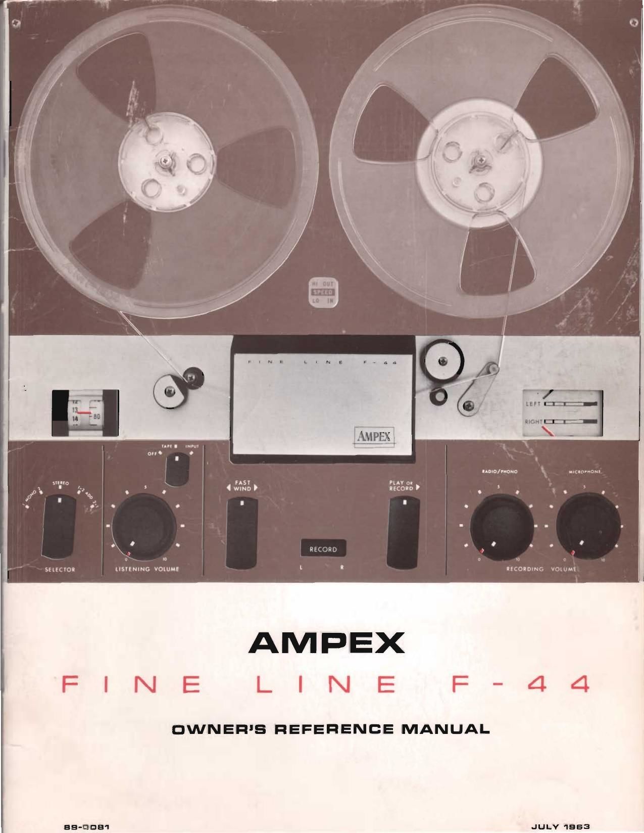
Ampex F 44 Owners Manual

This is the 28 pages manual for Ampex F 44 Owners Manual.
Read or download the pdf for free. If you want to contribute, please mail your pdfs to info@audioservicemanuals.com.

Page: 1 / 28
left right
Ampex F 44 Owners Manual

Extracted text from Ampex F 44 Owners Manual (Ocr-read)


Page 2

AMPEX

FINE LINE F-44

MODELS F-4450. F-4452, F-44SD, Sn F~447O

@fe/COMQ to the growing family
of music lovers whose discriminating tastes
have found expression in the ownership of an
AMPEX. Your new AMPEX recorder-a product
of the magnetic recording industrys most ad-
vanced skills-is designed to provide the high-
est levels of performance and dependability
attainable in any tape equipment made for
home or semi-professional use.

This manual has been prepared so that you
may realize the full potential of the quality
features engineered into your recorder. It is
suggested that you first read the manual care-
fully. operating the controls to become familiar
with their functions When you are ready to
perform the various functions, use of the index
at right will provide a convenient means of
locating the desired section.

WARRANTY REGISTERED

mug,

what does it consist of,
and what it does:

how to operate:

care and maintenance:

156

Page 7

The followin list outlines the controls, in-
dicators, and ot er functional parts used in
operating the Fine Line F-44 recorder. Num-
bers correspond with those in the illustration
on the opposite page. Note that LISTENING
VOLUME and RECORDING VOLUME con-
trols have double knobs; inner knob and sur-
rounding ring are separate controls.

Power and monitor switch. Switches re

corder on and selects monitoring of input
or tape. In INPUT position, signals from input
of recorder are present at output. In TAPE
position, signals rom tape are present at out-
put.

Selector switch Selects monophonic or

stereophonic recording and playback. In
MONO 1 position, input to left channel (from
microphone, radio, etc.) is recorded on upper
track (track 1 or 4). In MONO 2 position, in-
put to left channel is recorded on lower track
(track 3 or 2). In STEREO. inputs to both
channels are recorded simultaneously (on
tracks 1 and 3 or tracks 4 and 2). See page 23
for explanation of two ADD positions. Also see
page 10 for explanation of track placement
on tape.

Listening volume control. Inner knob ad-

justs listening volume for left channel,
and outer knob adjusts listening volume for
right channel. NOTE: In model F4452, lis-
tening volume is not adjustable and RADIO/
PHONO RECORDING VOLUME controls (see
#7) occupy this position.

Fast wind control. Moves tape rapidly in

either direction. To operate, turn knob in
direction of desired tape motion.

Record switch. Record switch (pushbut-

ton) is safety-interlocked with PLAY OF.
RECORD control (#6) - both must be actu~
ated simultaneously to record.

a Play or record control. Locks machine in
playback or recording mode of operation.
Turn clockwise to move tape at normal speed
from left to right.

0 Radio / phono recording volume. Inner
knob adjusts recording volume of external
input signal (such as a radio) for left channel
and outer knob adjusts recording volume for
right channel. NOTE: In model F-4452,
RADIO /PHONO RECORDING VOLUME con-
trols occupy position #3 and the MICRO-
PHONE RECORDING VOLUME controls (#8)
occupy this position.

Microphone recordin volume. Inner knob

adjusts recording vo ume of microphone
input signal for left channel and outer knob

AMPEX

FINE LINE F-44

adjusts recording volume for right channel.
NOTE: In model F-4452, MICROPHONE RE-
CORDING VOLUME controls occupy position
#7 and MICROPHONE INPUT jacks (#15)
occupy this position.

Record level meter. Upper meter indicates

recording level of upper track (marked
LEFT) and ower meter indicates recording
level of lower track (marked RIGHT).

0 Tape position indicator. Indicates starting
and stopping position of the various selec-
tions on the tape, enabling return to any pre-
determined position.

Speed selector. Selects tape speed: up posi-

tion for 71/2 ips. down for 3% ips. NOTE:
Recorder must be turned on when changing
tape speed setting.

Record indicators. Indicates which track is

actually being recorded; indicator marked
L (left) is upper track and indicator marked
R (right) is lower track.

Capstan and capstan idler. Capstan drives

tape at proper tape speed in play or record
modes. Capstan idler presses tape against cap-
stan and is only actuated in play or record
modes.

Automatic shut-off arm. Shut-off arm auto-

matically stops tape motion at end of reel
or if tape breaks. See Special Features on
page 14.
a Microphone input jacks. On the E4450

and 17-4460, microphone input jacks are
located on right side of recorder near front.
Upper jack is for left channel and lower jack
for right channel. 0n the F 4452, microphone
input jacks are located on top in position
normally occupied by MICROPHONE RE-
CORDING VOLUME controls (#8).
a Line input jacks. Line input jacks are lo-

cated at back of recorder near left side.
Line input jacks are used to connect a radio,
phonograph or other sound source to recorder.

Output jacks. Located on same panel as

line input jacks, output jacks are used to
connect recorder to amplifier-loudspeaker sys-
tems.

Power receptacle. Connected to proper

power source, receptacle provides power
to recorder. It is located on same panel as line
input and output jacks.

Auxiliary power outlet. Provides power to

auxiliary units such as the AMPEX 2044
Speaker-Amplifier and is controlled by recorder
power switch (#1). See Special Features on
page 14.