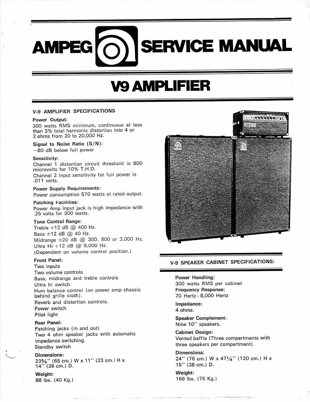
Ampeg v 9 service manual

This is the 5 pages manual for ampeg v 9 service manual.
Read or download the pdf for free. If you want to contribute, please mail your pdfs to info@audioservicemanuals.com.

Page: 1 / 5
left right
ampeg v 9 service manual

Extracted text from ampeg v 9 service manual (Ocr-read)


Page 1

AMPEG - SERVICE MANUAL

V9 AMPLIFIER

V-9 AMPLIFIER SPECIFICATIONS

Power Output:

300 watts RMS minimum, continuous at less
than 3% total harmonic distortion into 4 or
2 ohms from 20 to 20,000 Hz.

Signal to Noise Ratio (S/N):

-80 dB below full power

Sensitivity:

Channel 1 distortion circuit threshold is 800
microvolts for 10% T.H.D.

Channel 2 input sensitivity for full power is
.011 volts.

Power Supply Requirements:

Power consumption 570 watts at rated output.
Patching Facilities:

Power Amp input jack is high impedance with
.25 volts for 300 watts.

Tone Control Range:

Treble :12 dB @ 400 Hz.

Bass :12 dB @ 40 Hz.

Midrange :20 dB @ 300, 800 or 3,000 Hz.
Ultra Hi +12 dB @ 8,000 Hz.

(Dependent on volume control position.)

Front Panel:

Two inputs

Two volume controls

Bass, midrange and treble controls
Ultra hi switch

Hum balance control (on power amp chassis
behind grille cloth).

Reverb and distortion controls.

Power switch

Pilot light

Rear Panel:

Patching jacks (in and out)

Two 4 ohm speaker jacks with automatic
impedance switching

Standby switch

Dimensions:

235/5" (65 cm.) W x11" (23 cm.) H x
14 (36 cm.) D.

Weight:
88 lbs. (40 Kg.)

V-9 SPEAKER CABINET SPECIFICATIONS:

#

Power Handling:

300 watts RMS per cabinet
Frequency Response:

70 Hertz« 8,000 Hertz

Impedance:
4 ohms.

Speaker Complement:
Nine 10" speakers.

Cabinet Design:
Vented baffle (Three compartments with
three speakers per compartment).

Dimensions:
24" (76 cm.) W x 47% (120 cm.) H x
15" (38 cm.) D.

Weight:
166 lbs. (75 Kg.)

Page 2

V9 TONE P.C. BOARD
(VIEWED FROM COPPER SIDE)

DISASSEMBLY INSTRUCTIONS

BACK PANEL 3. Release perforated back panel
by means of 18 screws.

b. Un-plug the fan before completely removing
the back cover.

POWER CHASSIS a. Turn chassis on its side.
b. Remove 8 screws or bolts from the bottom
of the cabinet. c. Remove pre-amp wire
harness by disconnecting plastic plug.

d. Return cabinet to its normal position and
remove power chassis.

PRE-AMP a. Remove the 4 screws from the
inside of head cabinet. b. Push pre-amp
forward from inside of head cabinet.

BAFFLE

1. On older models the baffle is removable
only by un-screwing the nuts from the
single screws on either side of the baffle.
The baffle is then removable if a slight
tap is given from the inside to release the
plastic head lock.

2. On new models the baffle is removable
without removing the back panel. Use a
long rod and tap the baffle free from the
headlock retainers. Gain access from the
rear of the cabinet by using the space
available through the cooling fan blades.
The removal of the baffle will enable the
bias to be adjusted without the necessity
of disassembling the entire head cabinet.

CALIBRATION PROCEDURE

Connect a 4 ohm 330W minimum load to

speaker terminals.

Output stage bias current adjustment. (The

bias can be adjusted by removing the

head cabinet baffle. Use a long rod and

tap the baffle free from the headlock

retainers. Gain access from the rear of the

cabinet by using the space available

through the cooling fan blades.)

a. Adjust VR1 for 0.072 VDC between
K1 and ground.

b. Adjust VRZ for O 10.01 VDC between
K1 and K2.

Phase inverter balance control adjustment.

a. Harmonic distortion meter method-
Drive amplifier to 25 Volts R.M.S. out
at 40 Hz. and connect distortion meter
to load resistor. Adjust VR3 for
minimum distortion.

b. Volt meter method -
Adjust output as in step 3-A and
conn D.C. volt meter between testing
points K1 & K2, adjust VR3 for zero
1201 volts.

/////

unungus.

m

k;

(B) scar-ls on mus
DH £7.13 P CAWNEI \