Ampeg svp pro specs en

This is the 2 pages manual for ampeg svp pro specs en.
Read or download the pdf for free. If you want to contribute, please mail your pdfs to info@audioservicemanuals.com.

Page: 1 / 2
left right
ampeg svp pro specs en

Extracted text from ampeg svp pro specs en (Ocr-read)


Page 1

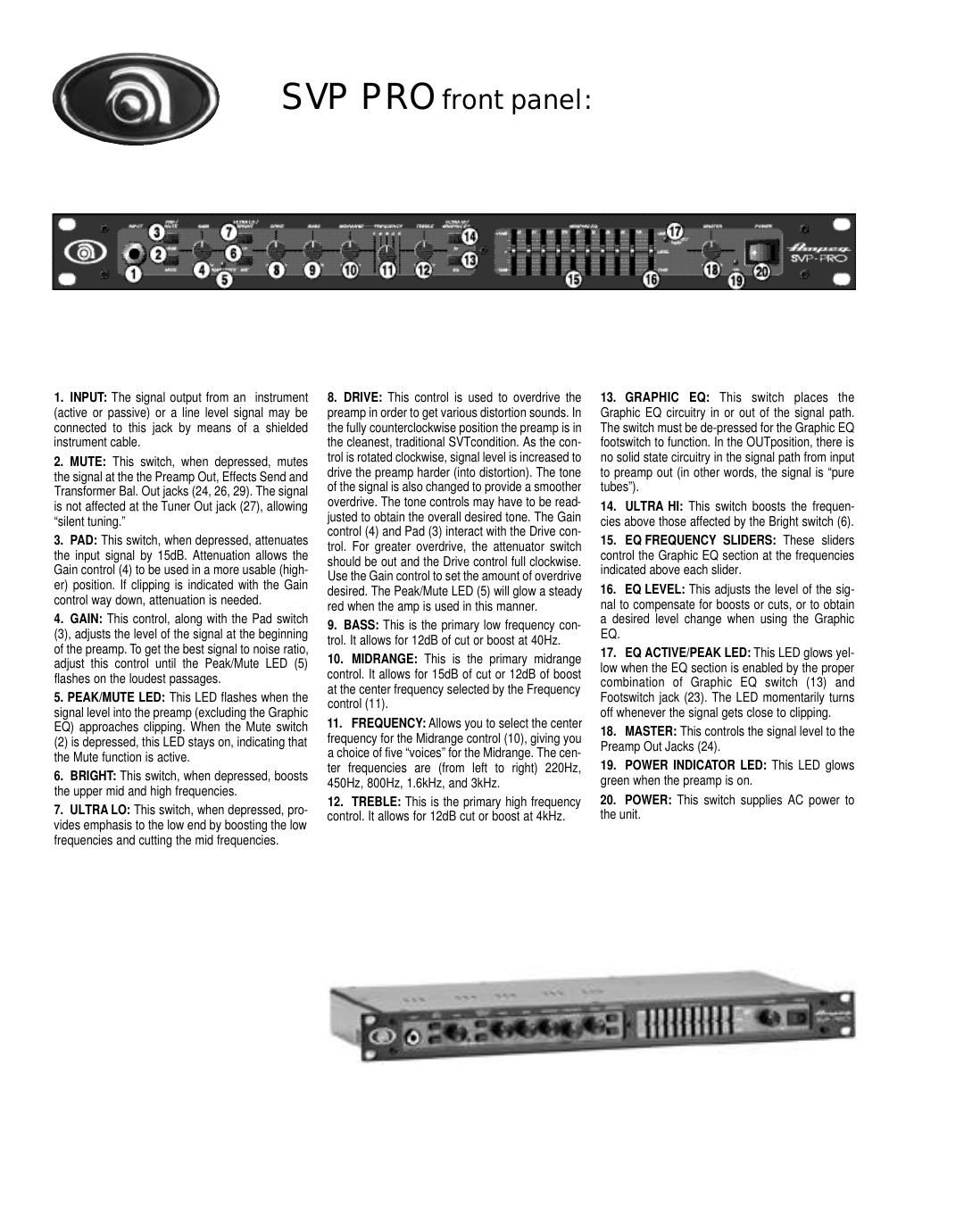
21.AC LINE IN: Firmly insert the supplied AC power cord into this socket until it is fully seated. Plug the male end of the cord into a grounded AC outlet. DO NOT DEFEAT THE GROUND PRONG OF THE AC PLUG! 22.AC LINE SELECTOR: This switch selects the proper AC line voltage to match the preamp to the available AC mains. Make sure it is in the proper position. 23.FOOTSWITCH: This is a stereo jack which will operate with a standard dual footswitch. The tip of the plug controls the Mute operation, the ring controls the Graphic EQ operation, and the sleeve acts as a ground common to both. With the footswitch inserted, both the front panel and the footswitch Mute switches are active. The front panel Graphic EQ switch (13) must be depressed for the Graphic EQ foot-switch to operate.24.PREAMPOUTS: These jacks carry the post- Master (18) signal. This signal is the main output which can be used to feed an external power amplifier, mixing console, or house PAsystem. 25.EFFECTS LOOPRETURN: This is a pre- Master (18) patch point return jack. It breaks the path through the preamp. When using an external signal processor, connect this jack to the OUTPUT of the processor by means of a shielded instru- ment cable. 26.EFFECTS LOOPSEND: This is a post-EQ, pre-Master (18) patch point send jack. It does not break the path through the preamp. When using an external signal processor, connect this jack to the INPUTof the processor by means of a shielded instrument cable.27.LEVEL: This control adjusts the level of the signal at the Balanced Out jack (29). 28.PRE/POST:This switch selects a direct out from the bass (Pre) in the OUTposition and the preamp signal just before the Master (18) (Post) in the depressed position. The selected signal is sent to the Balanced Out jack (29). 29.TRANSFORMER BALANCED OUT: T h i s XLR-type jack is the output for the signal selected by the Pre/Post switch (28). This signal can be used to feed an external power amplifier, mixing console, or house PAsystem. 30.TUNER OUT:This jack is a direct output from the instrument. It is the only output that stays active when the Mute switch is depressed.16 SVP PRO rear panel: Technical Specifications: TOTALSYSTEMGAIN58dB, @ 1kHz with levels up and tones flat, -3dB @ 30Hz and 15kHz TONECONTROLRANGE BASS:±12dB @ 40Hz MIDRANGE:+12,-15dB @ selected frequency (220, 450, 800, 1.6k or 3kHz) TREBLE:±12dB @ 4kHz ULTRALO:+3dB @ 40Hz, -12dB @ 500Hz ULTRAHI:+8dB @ 8kHz BRIGHT:+7dB @ 2kHz GRAPHICEQRANGE/LEVEL±12dB @ 40Hz, 90Hz, 180Hz, 300Hz, 500Hz, 1kHz, 2kHz, 4kHz, 10kHz; Level = +8, -10dB SIGNALTONOISERATIO80dB typical TUBECOMPLEMENT12AX7 (4), 12AU7 (1) POWER REQUIREMENTS120VAC, 60Hz, 28VA; 100/120VAC, 50/60Hz, 28VA; 230VAC, 50/60Hz, 28VA SIZE ANDWEIGHT19 W x 1.75 H x 10 D, 9 lbs.