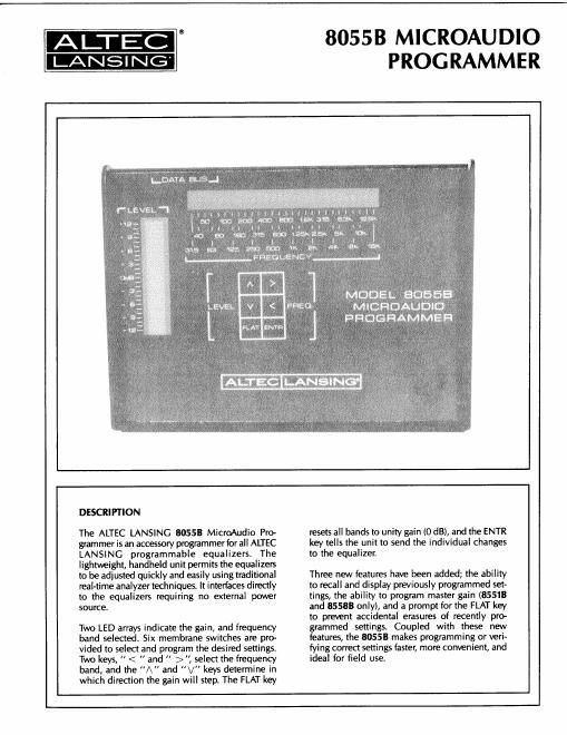
Altec 8055b manual

This is the 4 pages manual for altec 8055b manual.
Read or download the pdf for free. If you want to contribute, please mail your pdfs to info@audioservicemanuals.com.

Page: 1 / 4
left right
altec 8055b manual

Extracted text from altec 8055b manual (Ocr-read)


Page 2

SPECIFICATIONS

Controls: 6 - membrane switches

(K, >, /\ , V,FLAT, ENTR)

1 - momentary read switch

(rear panel)
Displays:
Frequency Band: 28 by 1 LED array, horizontal
Gain: 25 by 1 LED array, vertical
Connectors: 9-pin male D-subminiature
Color: Black
Dimensions: 8.25 in W x 6.13 in D x
2.25 in H
3.2cme2.4cme
0.9 cm H

ARCHITECTS AND ENGINEERS SPECIFICATIONS

The programmer shall interface directly to the
805518 or 805583 programmable one-third octave
equalizers, and be fully backwards-compatible with
earlier models. It shall have two LED arrays to in
dicate the frequency band seleded and the amount
of boost or cut in 1 dB step sizes. Membrane
switches shall be provided for the following six func-
tions: increment the frequency band, decrement the
frequency band, increment the gain, decrement the
gain, reset all bands to unity gain, and transmit the

Weight: 1.5 lbs (0.68 kg)

Included Accessories: 1 - communications cable
(9-pin male to 9-pin female)

Power Requirements: Provided by equalizers

ALTEC LANSING continually strives to improve pro
ducts and performance. Therefore, specifications are
subject to change without notice.

setting to the equalizer. A momentary switch shall
be provided to recall a setting from an equalizer. The
programmer shall also be ca able of programming
master gain in the 8551 B an 85588 programmable

equalizers. The programer shall be powered solely

from an equalizer and be provided with the proper
communications cable.

The programmer shall be the ALTEC LANSlNG

model 80553 MICROAUDIO PROGRAMMER.

ALTEC @
-

P.0. BOX 26105, OKLAHOMA CITY, OKLAHOMA 73126-0105, U.S.A.
©1939 ALTEC LANSING CORPORATION

PRINTED IN U.S.A. 589-3.5M

AL-1239
42-07-026145