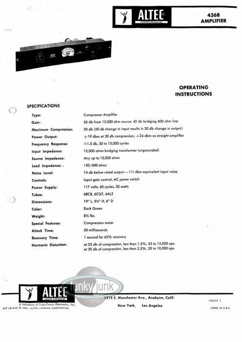
Altec 436b amplifier

This is the 4 pages manual for altec 436b amplifier.
Read or download the pdf for free. If you want to contribute, please mail your pdfs to info@audioservicemanuals.com.

Page: 1 / 4
left right
altec 436b amplifier

Extracted text from altec 436b amplifier (Ocr-read)


Page 1

DESCRIPTION The 436B Amplifier is a self-powered unit which occupies 3 W of rack space, with input gain control, power switch, fuse, pilot light and compression meter mounted on a hinged front panel. It is equipped with a bridging input transformer. Output loads of 150 or 600 ohms may be accommodated. The threshold and amount of compression, as well as the attack and recovery time of the circuit, are fixed quantities considered optimum for average program service. APPLICATIONS The 436B Amplifier is intended for use in automatic level control applications in public address systems. It may be used to control level differences between two or more medium-level program sources or as a program line compressor, or it may be used for automatic fading for voice-over-music announcements. Level differences caused by individual voice intensities and unequal distances of performers from the microphone, where single microphone pickup is employed, can be minimized by the use of the 436B Compressor. In industrial locations where sudden high level sounds might cause "blasting" with attend¬ ant danger to amplifiers and loudspeakers, the 436B Amplifier will prevent such overloading. The 436B can be used as a line amplifier by simply removing the 6AL5 tube from its socket. INSTALLATION AND OPERATION The design of the 436B Compressor Amplifier is versatile enough that it can be connected into any high- or low-impedance line between preamplifiers and power amplifiers, without adapters or other modification. In high-impedance lines, as exemplified by the Altec Lansing 1500 series P.A. amplifiers, the bridging input transformer of the 436B Amplifier provides a suitable load for the mixer-preamplifiers. The output of the 436B Amplifier, when ter¬ minated with 600 ohm resistance, is of sufficient level to operate directly into the high impedance of the power amplifiers. Where it is desired to insert the 436B into a transmission line of 500/600 ohms, a resistive termination of 600 ohms should be installed and the input of the 436B Amplifier connected across this load. The 600 ohm output then provides a suitable source for the input of the following power amplifier. A 600 ohm line level of +7 dbm (1.7 volts) will drive the 436B Amplifier to full 30 db compression, with a level of +19 dbm at the output of the compressor. Since this level is great enough to overdrive most power amplifiers, it is necessary to install a suitable loss pad at the input of the power amplifier, unless the power amplifier is already equipped with a gain control. Level Adjustments For unattended sound reinforcement systems in lecture halls and other places where the microphone and loudspeaker are in the same room, precautions must be taken to prevent acous¬ tic feedback when no performer is at the microphone. Level¬ setting procedure for this case is as follows: adjust input gain so that the average voice speaking at a normal distance from the microphone causes the meter on the 436B Amplifier to indi¬ cate 5 db of compression. Then ,in the absence of the per¬ former, adjust the power amplifier gain to the maximum level available without acoustic feedback. With this level adjust¬ ment, the weaker voices are reinforced the maximum possible. Louder voices will automatically be compressed. Where the microphone is not in the same location as the loud¬ speaker, input levels to the 436B Compressor Amplifier should be adjusted so that average program material will drive the compressor into 10 to 15 db of compression, as indicated on the meter. System output should then be set for appropriate volume by means of the power amplifier gain control. With the levels adjusted as above, input variations of ±15 db from average program level will result in only ±5 db change at the output of the 436B Amplifier. When it is desired to automatically fade "background" music for voice announcements, the gain control of the music chan¬ nel should be set so that for average music level, the com¬ pression threshold is barely reached. Proper listening level is then set by means of the power amplifier gain control. The voice channel gain control is adjusted to provide approxi¬ mately 25 db of compression, as shown on the meter, during normal announcements. The above settings will result in announcements at a level approximately 15 db above the original music level, same time, the music will drop to a level ab< the announcement level. SERVICING All circuit components are easily reached by opening the hinged front panel of the unit. Normal servicing can be done with a voltmeter. All pertinent information is shown on the schematic. 436B Amplifier Average Compression Characteristics 50 45 40 35 30 OUTPUT 25 DBM 20 COMPRESSION METER It is usually desirable to have the compression m from the operating position. When conditions dictate a location for the 436B Amplifier, an Altec #6049 meter sh be ordered for installation at the console. The additional meter is connected in parallel with the 436B Amplifier meter by means of a pair of wires extended to the console location. I 4 i \vOv R\vl UPRESSH k\\"1 I \p\ p y\\ 10 20 30 ^O 50 60 DB INPUT ABOVE THRESHOLD

Page 2

typical applications Fig. 1 The 436B Amplifier in typical high impedance line. A 600 ohm terminating resistor must be connected across the output of the 436B as shown. Fig. 2 Fig. 3 A typical low impedance line installation. The remote fader serves as proper termination for the 436B. Low impedance line with remote submasters. The 600 ohm terminating resistor must be installed at the the 436B Amplifier. The 1550A Apparatus Unit feeding the 436B should be strapped for a secondary p 17,500 ohms. FIG.2 Qfnky® PARTS LIST C2, 3, 5, 6 .022 mfd, 400 V., Micamold Tropicap pi Altec Lansing 13021 C4 1 mfd, 200 V., Astron ML-2-IM T1 Peerless 4651A C 7 80 mfd, 350 V., Mallory FP-138 T2 Peerless 16402 C8 80-40-10 mfd/200-450-450 V., Mallory FP 370 T3 # Peerless 6216 R3, 4 47,000 ohms, ±1%, Vi watt. Deposited Carbon Ml Altec Lansing 6049 R5, 6, 9 1 megohm, ± 10%, 'A watt PL1 Mazda #44 R7 220 ohms, ± 10%, } A watt FI V 2 amp 3AG Fuse R8 34 ohms, ±1%, Vi watt, Deposited Carbon SI Altec Lansing 12180 R10, 11 220,000 ohms, ± 10%, y A watt Rectifier Sarkes Tarzian 58-D R12 33,000 ohms, ± 10%, V 2 watt VI 6BC8 Vacuum Tube R13 10,000 ohms, ± 10%, 1 watt V2 6CG7 Vacuum Tube R14 6,800 ohms, ± 10%, 1 watt V3 6AL5 Vacuum Tube