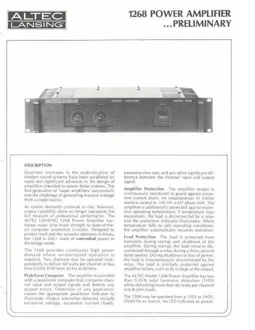
Altec 1268 service manual

This is the 8 pages manual for altec 1268 service manual.
Read or download the pdf for free. If you want to contribute, please mail your pdfs to info@audioservicemanuals.com.

Page: 1 / 8
left right
altec 1268 service manual

Extracted text from altec 1268 service manual (Ocr-read)


Page 1

ALTEC

1268 POWER AMPLIFIER
PRELIMINARY

POWER Aix/lFLlFtEFI

MODEL 1 268

DESCRIPTION

Quantum increases in the sophistication of
modern sound systems have been paralleled by
rapid and significant advances in the design of
amplifiers intended to power these systems. The
first generation of super amplifiers successfully
met the challenge of generating massive wattage
from a single source.

As system demands continue to rise, however,
output capability alone no longer represents the
full measure of professional performance The
ALTEC LANSING 1268 Power Amplifier har~
nesses super amp brute strength to state art Computer protection circuitry. Designed to
protect itself and the acoustic elements it drives,
the 1268 is 200+ watts of controlled power in
the bridge mode.

The 1268 provides continuous high power
demand where uninterrupted operation is
requisite. Two channels may be operated inde-
pendently to deliver 60 watts per channel at less
then 0.03% THD from 20 Hz to 20 kHz.

Peak/Error Computer The amplifier is provided
with a peak/error computer that compares chan-
nel input and output signals and detects any
output errors. Detection of any peak/error
causes the appropriate peak/error indicator to
illuminate. Output anomalies detected include
excessive voltage, excessive current (load),

excessive slew rate, and any other significant dif-
ference between the channel input and output
signal.

Amplifier Protection The amplifier output is
continuously monitored to guard against exces-
sive Current drain. An instantaneous Vl limiter
restricts output to 100 VA 145° phase shift. The
amplifier is additionally protected against exces-
sive operating temperature; if temperature rises
excessively, the load is disconnected by a relay
and the protection indicator illuminates. When
temperature falls to safe operating conditions,
the amplifier automatically resumes operation.

Load Protection The load is protected from
transients during startup and shutdown of the
amplifier. During startup, the load remains dis-
connected through a relay during a threevsecond
delay period. During shutdown or loss of power.
the load is instantaneously disconnected by the
relay. The load is similarly protected against
amplifierfailure, such as dc voltage at the output.

The ALTEC Model 1268 Power Amplifier has less
than 0.05% total harmonic distortion (THD)
while delivering more than 60 watts per channel
into 8-ohm loads.

The 1268 may be operated from a 120V or 240V,
50/60 Hz ac source. An LED indicates ac power.

1)

Page 2

k

SPECIFICATIONS:
Type: Twoechannel basic power amplifier

Power Gain: 46.5 dB (balanced) bridging GOO-ohm
line with arohm load

52.5 dB (balanced) bridging 60070hm line
in bridge (mono) mode with 8~ohm load
29.0 dB (unbalanced)

0.77SV rms for rated output

Voltage Gain:
Input Sensitivity:

Power Output: 60 watts per channel into 8 ohms, both
channels driven from 20 Hz to 20 kHz at
less than 0.03% THD

Typically greater than 75 watts per
channel into 8 ohms at 1 kHz at less
than 0.01 /u THD

Bridge (mono)
Operation: Typically greater than 200 watts into 8 ohms

from 20 Hz to 20 kHz at less than 0.05% THD

lM Distortion
(single channel): Less than 0.03% from 001 watt to 60

watts into 8 ohms (60 Hz, 7 kHz, 4:1)

Frequency
Response
(direct input): :0.25 dB at 1W (8 ohms) from 20 HZ to
20 kHz +0 dB, -3 dB at 1W (8 ohms)

from 5 Hz to 100 kHz

Input Impedance: 15,000 ohms (nominal for all inputs)

Load Impedance: 4 ohms or greater 145° or less
8 ohms or greater :45" or less
in bridge (mono) mode

Output
Impedance: Less than 0.1 ohm in dul mode all kHz
Less than 02 ohms in bridge (mono)
mode at 1 kHz

Signal-to-Noise

Ratio: Greater than 100 dB unweighted with
GOO-ohm source impedance volume
at maximum

Channel

Separation: Greater than 70 dB at I kHz

ARCHITECTS AND ENGINEERS SPECIFICATIONS

The power amplifier shall be capable of operating
from a 120/240V ac, 50/60 Hz line. Circuitry shall
provide protection for the output transistors and
theload.

The power amplifier shall meet the following criteria.
Gain: 46.5 dB with line transformer bridging
GOO-ohm line with 8-ohm load. Input sensitivity:
0.775V rms for rated output. Power output: 60 watts
per channel into 8 ohms, both channels driven from
20-20,000 Hz at less than 0.03% THD. Frequency
response with direct input: $0.25 dB at 1W (8 ohms)
from 20-20,000 Hz. Input impedance (nominal):

Slew Rate: 1 8 V/p. sec

2 stepped attenuators

1 MODE switch (mono or dual operation)
1 ac POWER ON-OFF switch

1 ac power indicator (LED)

2 peak/error indicators (LED); indicate
excessive inpquutput differential for
each channel; shows THD greater than
1% and transient errors. Response time:

1 microsecond with 25 millisecond hold
iorvisibility.

1 PROTECTION indicator (LEDl; indicates
operation of load/amplifier protection
system.

2 channel input receptacles (Can non type)
4 channel outputjacks (5~way binding
9051 WW)

2 phonejack multiple receptacles (to
connect additional amplifiers)

840m, 3-wire. 166A power cord with
NEMA 5715 plug

Controls:

Power
Requirements: 120/240V ac, 50/60 Hz 50W at zero signal
150W at /2 rated output (8 ohms) with
both channelsdriven ati kHz

225W at rated outpUt (8 ohms) with both
channelsdriven at 1 kHz

Amplifier
Protection: Active output stage wrth voltage/current

limiting. Temperature sensor.

Load Protection: Output relay delays turn-on of output
power for 3 seconds. Provides instant
turn-cit of output power and removal of
load during presence of dc voltage in
output] or in event of excessive heat
sink temperature

Operating
Temperature
Range: Up to +55°(131°Fi ambient
Dimensions: 3V2 (8.9 cm) H
19 (48.3 Cm) W
10" (25.4 cm) D
Color: Black
Enclosure: Rack mount chassis with

heavy duty front handles

15,000 ohms. Load impedance: at least 4 ohms/
channel; at least 8 ohms in bridge (mono) mode.
Output impedance: less than 0.1 ohm in dual mode
at 1000 Hz; less than 0.2 ohm in bridge (mono) mode
at 1000 Hz. Signal-to-noise ratio: more than 100 dB
unweighted with BOO-ohm source impedance volume
at maximum. Channel separation: more than 70 dB
at 1000 Hz. Operating temperature range: up to 55°C
(131°F) ambient. Dimensions: 3% H x 19 W x
10 D. Color: black. Enclosure: rack mount chassis
with heavy duty front handles.

The power amplifier shall be the ALTEC Model 1268.

ALTEC

1515 SOUTH MANCHESTER AVENUE, ANAHEIM, CALIFORNIA 92803
AlTEC CORPORATION

LITHO IN U.S.A. 981-2.5M

/

ALrZ 506-2