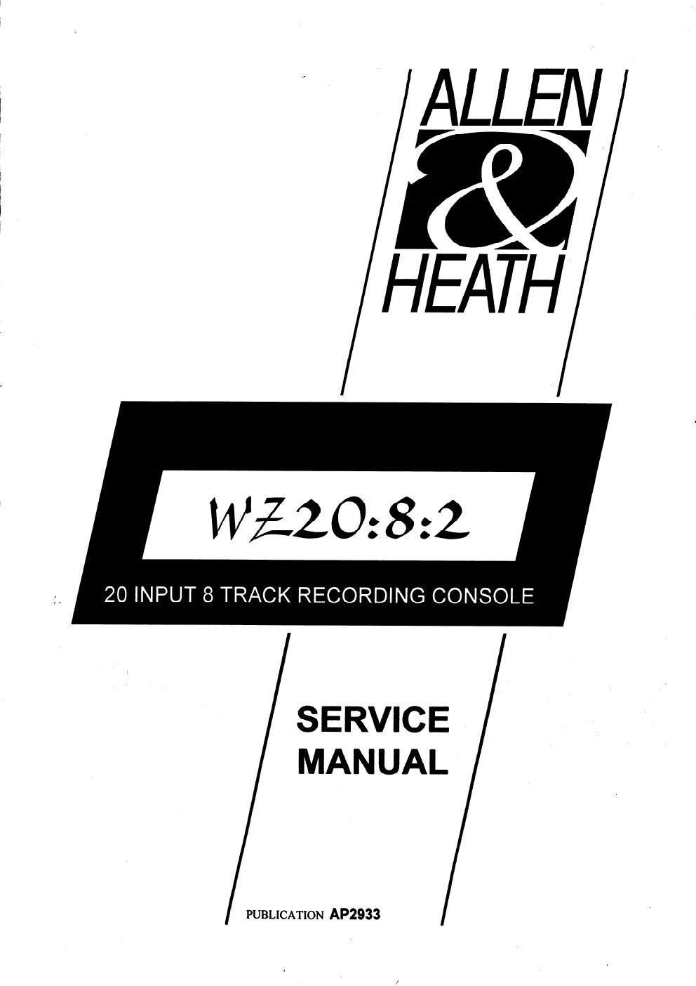
Allen heath wz2082 service manual

This is the 34 pages manual for allen heath wz2082 service manual.
Read or download the pdf for free. If you want to contribute, please mail your pdfs to info@audioservicemanuals.com.

Page: 1 / 34
left right
allen heath wz2082 service manual

Extracted text from allen heath wz2082 service manual (Ocr-read)


Page 1

ALLEN & HEATH 2 2E-8SM CONTENTS INTRODUCTION, SERVICE AND TECHNICAL SUPPORT............................................................................. 2 TECHNICAL DESCRIPTION............................................................................................................................. 3 SPECIFICATION & CONNECTIONS................................................................................................................. 4 DIMENSIONS FOR FLIGHTCASING, INSTALLING THE CONSOLE.............................................................. 5 REMOVING THE CONNECTOR CIRCUIT BOARD .......................................................................................... 6-7 REMOVING A MONO or STEREO INPUT, LEFT or RIGHT CIRCUIT BOARD .............................................. 8-9 INTERNAL LINK OPTIONS............................................................................................................................... 10-11 ORDERING A CONSOLE, SPARE PARTS & ASSEMBLIES.......................................................................... 12-14 FRONT & REAR PANELS................................................................................................................................. 15 TRANSFORMER & POWER WIRING............................................................................................................... 16-17 MONO INPUT CIRCUIT BOARD COMPONENT IDENT.................................................................................. AG2894 MONO INPUT CIRCUIT DIAGRAM................................................................................................................... C2894 STEREO INPUT CIRCUIT BOARD COMPONENT IDENT..............................................................................AG2937 STEREO INPUT CIRCUIT DIAGRAM............................................................................................................... C2937 LEFT CIRCUIT BOARD COMPONENT IDENT................................................................................................. AG2938 LEFT CIRCUIT BOARD CIRCUIT DIAGRAM sheet 1 ...................................................................................... C2938 LEFT CIRCUIT BOARD CIRCUIT DIAGRAM sheet 2 ...................................................................................... C2938 RIGHT CIRCUIT BOARD COMPONENT IDENT.............................................................................................. AG2939 RIGHT CIRCUIT BOARD CIRCUIT DIAGRAM sheet 1 ....................................................................................C2939 RIGHT CIRCUIT BOARD CIRCUIT DIAGRAM sheet 2 ....................................................................................C2939 CONNECTOR CIRCUIT BOARD COMPONENT IDENT ..................................................................................AG2940A CONNECTOR CIRCUIT BOARD CIRCUIT DIAGRAM sheet 1........................................................................ C2940A CONNECTOR CIRCUIT BOARD CIRCUIT DIAGRAM sheet 2........................................................................ C2940A CONNECTOR CIRCUIT BOARD CIRCUIT DIAGRAM sheet 3........................................................................ C2940A CONNECTOR CIRCUIT DAUGHTER BOARD COMPONENT IDENT.............................................................AG2940B CONNECTOR CIRCUIT DAUGHTER BOARD CIRCUIT DIAGRAM............................................................... C2940B BLOCK DIAGRAM.............................................................................................................................................. 34 INTRODUCTION The information presented in this manual is intended for competent technical personnel to carry out service and product support for the MixWizard WZ 20:8:2. We assume that the reader is familiar with the related electronic theory and audio terminology, and is able to carry out basic servicing, fault-finding and repair of audio equipment of this type. Service personnel should also be familiar with audio systems, mains earthing and power requirements, as well as handling precautions. For further information on the operation and application of the MixWizard WZ 20:8:2 please refer to the USER GUIDE publication AP2932 supplied with each console. Whilst we believe the information in this manual to be reliable we do not assume responsibility for inaccuracies. We also reserve the right to make changes in the interest of further product development. SERVICE AND TECHNICAL SUPPORT Under normal conditions the MixWizard WZ 20:8:2 does not require user maintenance or internal calibration. Any service work required should be carried out by qualified technical personnel only. We are able to offer further product support through our worldwide distribution network. To help us provide the most efficient service please would you quote the console serial number in any communication regarding this product. copyright © 1997 ALLEN & HEATH. All rights reservedPublication..................... AP2933 Issue 1 SAFETY WARNING ! Mains electricity is dangerous and can kill. Mains voltage is present within the unit. Do not remove any covers with mains connected. Do not carry out any work within the unit while it is powered. High voltage components are insulated for safety but should not be touched with power applied. The mains voltage setting is indicated on the on the rear panel next to the mains socket. Check that this matches your local mains supply. Check your mains wiring and earthing before switching on. DO NOT REMOVE THE MAINS EARTH CONNECTION! The chassis is always connected to mains earth. Audio 0V connects to the chassis internally. Should problems be encountered with ground loops operate the audio ground lift switches on other equipment connected to the unit or disconnect the cable screens at one end. Refer to the section on 'EARTHING' in the User Guide.

Page 2

ALLEN & HEATH 2E-8SM 3 TECHNICAL DESCRIPTION The ALLEN & HEATH MixWizard WZ 20:8:2 is a dedicated 8-track rack mount or desk standing mixer with 8 mono inputs and 6 stereo inputs. All mono input channels have a 4 band 2-sweep EQ with 6 individual aux sends and Direct output. The 6 stereo inputs have a 2 band EQ with 2 stereo cue/aux sends and 2 mono aux sends. The 8 tape return inputs have individual level and pan controls with a stereo cue facility . In addition the MixWizard WZ 20:8:2 also has extensive talkback facilities and an internal 1kHz sinewave oscillator for level checking The internal power supply unit is located in the rotating connector module. CONSTRUCTION All metal chassis for 19" rack mount in 10U space. Comprises a 16swg steel front panel housing individual channel circuit assemblies interconnected by means of soldered copper wire busbars. The connectors are housed in a rotating connector module for either rack or desk mounted applications. Access to the channel internal assemblies is by removal of the 18swg folded steel base. Access to the connectors and power supply components is by removal of the rear cover of the connector module without the need to remove the console base. The channel assemblies may be removed for servicing. THE CIRCUIT COMPONENTS The MixWizard WZ 20:8:2 is manufactured using high performance industry standard linear op-amp and discrete semiconductor circuit devices. In particular the switches and potentiometers have proven to be durable and problem free. When operated correctly the normal performance of the unit introduces no noticeable audio signal degradation. AUDIO INPUTS AND OUTPUTS All XLR connector inputs and outputs are balanced (differential) with high impedance inputs and low impedance outputs. To use these with unbalanced equipment the -ve signal should be linked to 0V in the cable or input connector. All unbalanced connections are line level 3-pole TRS ¼" jack sockets. All outputs are low impedance and thus capable of driving several high impedance inputs simultaneously. All inputs and outputs are in phase. THE PFL SYSTEM The console PFL switches send pre-fade signals to the PFL mix bus. These signals are switched with 4053 CMOS gates located on the RIGHT circuit board (PCB No: AG2939). The supply for the 4053 is ± 8V DC and is derived locally from the ±16V. The gates are switched when a PFL switch is selected. EARTHING THE AUDIO SYSTEM The console chassis is connected to mains earth via the mains power cable. Console audio 0V is also connected to chassis. FOR SAFETY REASONS NEVER REMOVE THE EARTH WIRE FROM THE MAINS PLUG. Multiple earth paths cause earth (ground) loops which may result in audible hum and interference. These may be avoided by making sure that there is only one path to earth from each piece of equipment, disconnecting audio cable screens at one end if necessary. INTERCONNECTIONS Where possible use balanced connections for the CHANNEL inputs, AUX/CUE SENDs, and both L/R outputs to minimise noise pick-up. Avoid running audio cables near to mains or lighting cables, thyristor dimmer units or power supplies etc. These may cause audible hum and buzz. The use of low impedance sources significantly reduces interference pick-up. Check the cables for correct wiring to avoid problems with phase reversal and unreliable connection. The MixWizard WZ 20:8:2 follows the convention for XLR pin 2 and jack tip = signal hot (+). ALWAYS USE BALANCED CABLES WHEN CONNECTING TO PHANTOM POWERED MICROPHONES. WHEN USING NON-PHANTOM POWERED OR UNBALANCED MICROPHONES OR UNBALANCED LINE SOURCES, MAKE SURE THAT THE +48V IS DISABLED TO PREVENT ACCIDENTAL DAMAGE. INDIVIDUAL CHANNELS CAN HAVE +48V DISABLED, REFER TO THE LINK OPTIONS SECTION IN THE USER GUIDE OR SERVICE MANUAL. If ground loops cause problems, connect the cable screen at one end only. Balanced outputs may be connected to unbalanced inputs and vice versa by linking the signal cold (-) to 0V ground.