This is the 5 pages manual for akg c 522 ms owners manual.
Read or download the pdf for free.
If you want to contribute, please mail your pdfs to info@audioservicemanuals.com.
AKG
OCOUSCICS
STEREO MlKROFON
STEREO MICROPHONE
MICROPHONE STEREO
MlOROFONO STEREO
MlOROFONO ESTEREO
0522 MS
Bedienungshinweise
User lnstructions
Mode d'emploi
lstruzioni dfusO
'Modo de empleo
General Description: Applications:
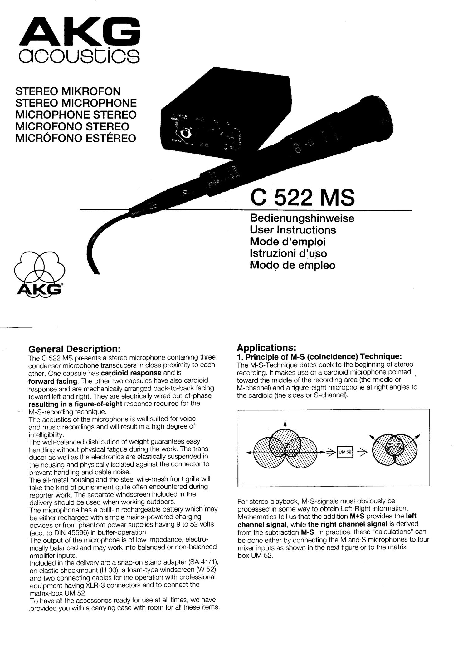
The C 522 MS presents a stereo microphone containing three 1. Principle of M-S (coincidence) Technique:
condenser microphone transducers in close proximity to each The M-S-Technique dates back to the beginning of stereo
other. One capsule has cardioid response and is recording. It makes use of a cardioid microphone pointed
forward facing. The other two capsules have also cardioi'd toward the middle Of the recording area (the middle or
response and are mechanically arranged back-tO-back facing M-channel) and a figure-eight microphone at right angles to
toward left and right. They are electrically wired out-Of-phase the cardioid (the Sides or S-channel).
resulting in a figure-of-eight response required for the
M-S-recording technique.
The acoustics Of the microphone is well suited for voice
and music recordings and will result in a high degree Of
intelligibility.
The well-balanced distribution Of weight guarantees easy (Q/441$ / M .\ .
handling without physical fatigue during the work. The tranS- \\\\\o:§:§:9:§3:§§32\\\ $- % @tsqqim}\\\
* //a\\\\
ducer as well as the electronics are elastically suspended in \ \Wfii W \\\\
the housing and physically isolated against the connector tO \\\\\\\\ \ \\
prevent handling and cable noise.
The all-metal housing and the steel wire-mesh front grille will
take the kind of punishment quite Often encountered during
reporter work. The separate windscreen included in the
delivery should be used when working outdoors. _ For stereo playback, M-S-Signals must Obviously be
The microphone has a built-in rechargeable battery which may processed in some way to Obtain Left-Right information.
be either recharged with simple mains~powered charging Mathematics tell us that the addition M+S provides the left
devices or from phantom power supplies having 9 to 52 volts channel signal, while the right channel signal is derived
(800- TO DIN 45596) in buffer-Operation. from the Subtraction M-S. In practice, these "calculations" can
The OUTDUt Of the microphone *8 Oi low impedance, electro- be done either by connecting the M ands microphones to four
nically balanced and may work into balanced or non-balanced mixer inputs as shown in the next figure or to thematrix
amplifier inputs. box UM 52,
Included in the delivery are a snap-on stand adapter (SA 41/1),
an elastic shockmount (H 30), a foam-type windscreen (W 52)
and two connecting cables for the operation with professional
equipment having XLR-S connectors and to connect the
matrix-box UM 52.
To have all the accessories ready for use at all times, we have
.provided you with a carrying case with room for all these items.
2. Boom Work:
For this kind of work we have supplied an elastic shockmount,
which may be fastened to the boom by a 8/8" or 5/8" thread.
Please refer to the enclosed manual for theH 30, explaining
the use of this accessory. "
5. The Usage of the Matrix UM 52:
12
For correct left/right orientation, be sure to mount the
microphone in such a way that the symbols shown always
face up.
3. Applications on Microphone Stands:
To mount the microphone on floor or table stands, a stand
adapter is enclosed. The SA 41/ i may be pushed onto the
microphone following the routine shown on the related sketch
explaining the handling of this accessory.
For correct left/right orientation, be sure to mount the micro-
phone in such a way that the symbols shown always face up.
4. Outdoor Work:
The included foam-type windscreen may be easily pushed
onto the microphone head by slightly turning the microphone
at the same time. .The windscreen should be always used
outdoors to prevent noise or drop-outs generated by sudden
gusts of wind or microphone movements.
11
Q) Selector switch to monitor either the Mid (mono) or the
Left/Right (stereo) signal
Bass cut / output attenuator
Selection" of output signal in M/S or X/Y when input signal
from the microphone in M/S
(9 Battery on/off switch
@ Battery test LED
@ Test button for the batteries in use
® S/M level balance (change of recording angle)
Volume control for the headphone output
@ Headphone output (1/4" stereo jack)
Input connection (to connect with microphone)
® Output connection (to connect with recording equipment)
® Battery compartment holding two 9 volt-batteries
(type lEC 6F22)
@ Self-locking lid for the battery compartment
Carrying bag '
The UM 52 provides the following functions:
a) convert the input signal -- M/S (mid-side) microphone
signal - into a X/Y (left-right) output signal to be used for sound
recording or transmission in broadcasting '
_ b) change of the recording angle of the microphone through
continuous variation of the side signal versus the mid-signal
S/M (d3) . _ ' '
c) headphonemonitoring of the mid (mono) signal or the left-
right (stereo) signal with built-in headphone amplifier and
volume control -
d) switchable bass-cut and -10 d3 output attenuation of the
micrOphone signal
e) testing facility for the batteries required for the monitor
amplifier