AKG C414BXLS XLII Service Manual

This is the 2 pages manual for AKG C414BXLS XLII Service Manual.
Read or download the pdf for free. If you want to contribute, please mail your pdfs to info@audioservicemanuals.com.

Page: 1 / 2
left right
AKG C414BXLS XLII Service Manual

Extracted text from AKG C414BXLS XLII Service Manual (Ocr-read)


Page 1

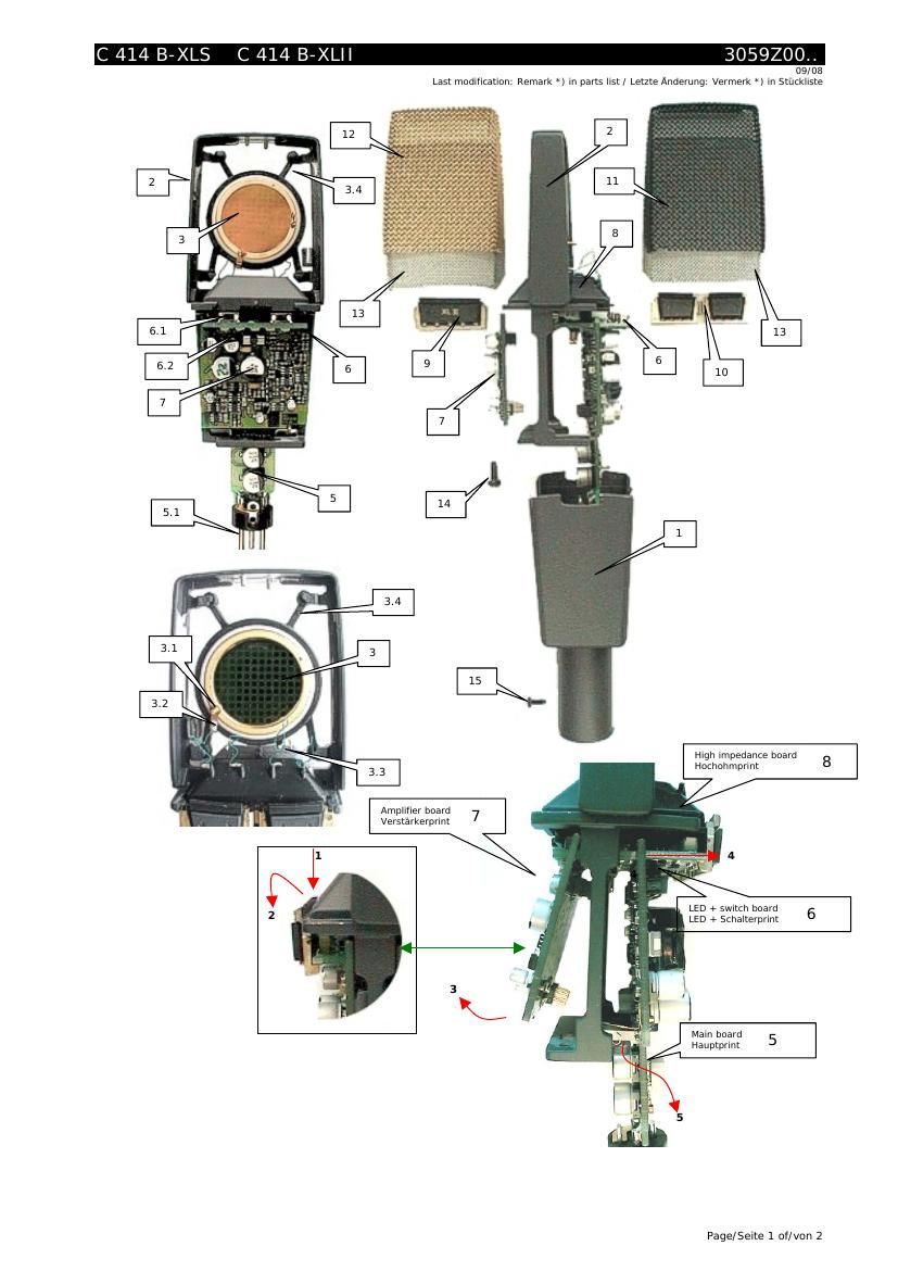
C 414 B-XLS C 414 B-XLII 3059Z00.. Page/Seite 2 of/von 2 C 414 B-XLS 3059Z0001-¦ A C 414 B-XLS/ST 3059Z0021 -¦ A C 414 B-XLII 3059Z0002 -¦ B C 414 B-XLII/ST 3059Z0022 -¦ B Description Pos. Part Nbr. Best.-Nr. A XLS B XLII Bezeichnung Housing 1 3059Z1011 1 - Gehäuse Housing 1 3059Z1012 - 1 Gehäuse Frame 2 3059Z1111 1 1 Rahmen Capsule CK12 3*) 2072Z0022 1 - Kapsel CK12 Capsule CK12 3*) 2072Z0023 - 1 Kapsel CK12 Screw for capsule connection 3.1 2072Z0802 2 2 Schraube fĂĽr Kapselanschluss Solder tag 3.2 4149N6059 2 2 LötflĂĽgel Stranded wire 3.3 2847Z3202 4 4 Litze Suspension 3.4 2820Z1401 1 1 Aufhängung Main Pcb complete 5*) 3059M0102 1 1 Hauptprint kpl. XLR -“ connector insert 5.1 0016E0379 1 1 XLR - Steckereinsatz Printed circuit board 2, complete (LED + switch board) 6 3059M0201 1 1 Print 2, komplett (LED + Schalterprint) Switch 6.1 9040E0011 6 6 Schalter LED red/green 6.2 9014E0054 5 5 LED rot/grĂĽn LED green 9014E0076 8 8 LED grĂĽn Printed circuit board 3, complete (amplifier) 7 3059M0301 1 1 Print 3, komplett (Verstärker) Printed circuit board 4, complete, with solder pins and cover (high impedance board) 8 3059M1201 1 1 Print 4, komplett, mit Lötfahnen und Abdeckung (Hochohmprint) Switch cover 9 3059M1701 1 - Schalterblende Switch cover 3059M1702 - 1 Schalterblende Switch cover 10 3059M1801 1 1 Schalterblende Grille, black 11 3059M1001 1 1 Gitter, schwarz Grille, silver 12 3059M1002 1 - Gitter, silber Grille, golden 12 3059M1003 - 1 Gitter, gold Inner grille 13 3059Z1301 2 2 Innengitter Screw M3x8 for housing 14 7500D3001 2 2 Schraube M3x8 fĂĽr Gehäuse Screw M2,5x6 for XLR 15 7500D2502 1 1 Schraube M2,5x6 fĂĽr XLR Hard case (not for ST versions) -- 3830P0002 1 1 Koffer (nicht fĂĽr ST Varianten) Hard case (for ST versions) -- 3828P3000 1 1 Koffer (nicht fĂĽr ST Varianten) Foam insert for ST case, upper -- 3828P0923 1 1 Schaumeinlage fĂĽr ST Koffer, oben Foam insert for ST case, lower -- 3828P0924 1 1 Schaumeinlage fĂĽr ST Koffer, unten Windshield W 414X -- 2802Z0301 1** 1** Windschutz W 414X Spider suspension H 85 -- 2803Z 0007 1** 1** Spinnenaufhängung H 85 Stereo bar H50 (ST versions only) -- 6000H0571***) 1 1 Stereoschiene (nur bei ST Versionen) Mic clip SA 60 (ST versions only) -- 6000H6001***) 1 1 Stativadapter SA 60 (nur bei ST Versionen) Pop filter PF 80 (not for ST versions) -- 6000H0632***) 1 1 Popfilter PF 80 (nicht fĂĽr ST Varianten) IMPORTANT! In case of a defective mainboard (5) please attend to the following. As a result of a new design of the mainboard (5 ) it is absolutly necessary to exchange also the high impedance board (8). In case of ordering the main board (5) as a spare part you will automatically get the high impedance board (8) additionally. *) In case that these parts need to be exchanged, the resultin g sensitivity may vary substantially from the original value. It is strongly recommended to, send those mics to AKG for repair. / Im Fall, dass diese Teile getauscht werden, kann die resultierende Empfind lichkeit wesentlich vom Originalwert abweichen. Es wird dringend empfohlen, solche Mikros zur Reparatur an AKG zu senden **) 2 pieces for 'ST' versions / 2 StĂĽck fĂĽr 'ST' Varianten ***) Not available via Service Dept. Can be ordered as a standard sales item ***) Nicht ĂĽber Service erhältlich. Kann als regulärer Vertriebsteil bestellt werden. Hints for disassembling Undo screws 14 and 15 and remove housing 1. Take off switch cover 9 from the front side of the mic (golden or silver grille). This can be done by pressing onto the cover at it's upper edge (ste p 1) and turning it towards the front (step 2). Now remove printed circuit board 7 as shown (step 3). Shift out board assembly consisting of item 6 and 8 (step 4) until board 5 can be taken away. Finally by slippi ng the board assembly completely out from it's guide parts 6 and 8 can be separated. When reassembling please watch for correct positioning and connection of all contacts between the various connectors of all pr inted circuit boards. Once one of the stranded wires 3.3 to the capsule is broken, it shall not be re-soldered but replaced !! Zerlegehinweise Lösen Sie Schrauben 14 und 15 und entfernen Sie das Gehäuse 1. Nehmen Sie die Schalterblende 9 an der Vorderseite das Mikrofons (goldenes oder silbernes Gitter) ab. Dies geschieht am einfachsten durch Druck in Richtung der Pfeils (Schritt 1) und gleichzeitiges heraus drehen nach vorne (S chritt 2). Jetzt Print 7 wie gezeigt entfernen (Schritt 3). Schieben Sie die Montagegruppe bestehend aus Teil 6 und 8 nach vor (Schritt 4) bis Print 5 abgenommen werden kann. Nun die Montagegruppe komplett aus ihrer FĂĽhrung schieben und Teile 6 und 8 trennen. Beim Zusammenbau achten Sie bitte auf richtige Positionierung und Verbindung aller Kontakte der verschiedenen Stecker und Prints. Falls Kapsellitzen 3.3 abbrechen, bitte nicht wieder anlöten, sondern unbedingt gegen neue Litzen tauschen ! AKG Acoustics GmbH, A Harman International Company, Lemböckgasse 21-25, A-1230 Wien, Austria Phone: (+431) 86654-0, Fax: (+431) 86654-1514, e-mail: service@akg.com