Akai X 360 D Service Manual

This is the 64 pages manual for Akai X 360 D Service Manual.
Read or download the pdf for free. If you want to contribute, please mail your pdfs to info@audioservicemanuals.com.

Page: 1 / 64
left right
Akai X 360 D Service Manual

Extracted text from Akai X 360 D Service Manual (Ocr-read)


Page 1

(0

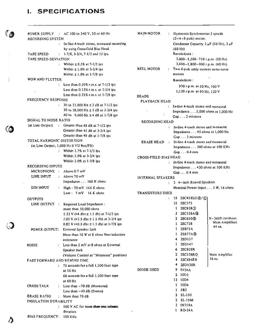
I. SPECIFICATIONS

POWER SUPPLY
RECORDING SY STEM

AC [00 lo 240 V, 50 or 60112

Inellne Muck stereo, monaural recording

by using Cross-field Bias Head.
TAPE SPEED 1.7/3, 3.3/4, 7-1/2 and 15 ips.
TAPE SPEED DEVIATION
Within 1 0.5% al7-1/21ps
Within i1.0% at 3-3/4 ips
Within 11.0% at 1-7/81ps
WOW AND FLUITER
Less than 0.10% rims. 317-112 11):
Less than 0.13% 1'.rn.s. a! 3-3/4 'rps
Less than 025% 11.5. at 1-7/8 ips
FREQUENCY RESPONSE
30 11) 21.000 Hz :3 1113 3174/2115:
30 to 18.000 Hz :3 (113 at 3-3/4 ips
40 10 9.000 Hz 14 dB at 1-7/8 1p:
SIGNAL TO NOISE RATIO
(at Line Oulput; Greater than 48 dB at 7-1/2 ips
Greater than 45 dB 31 3-3/4 ips
Greater than 48 dB a! 1-7/8 1ps
TOTAL HARMONIC DISTORTION
(:1: Line Output, 1.000 H1 0 VU Rec/PB)
Will'u'n 1.7% a! 7-1/2 ips
Wilhln 3.0% at 3-3/4 ips
Wlthin 3.0% at 1-7/8 ips
RECORDING INPUTS

MICROPHONE Above 0.7 mV
LINE INPUT Above 70 mV
Impedance... 166 K ahms
DIN INPUT High : 70_mV 166 K ohmx
Low: 7 11W 16 K ohms
OUTPUTS
LINE OUTPUT Required Load Impedance :

more than 50,000 011m:

1.13 V (+4 dbsi 1.5 db) at 7-1/2 ips
1.03 V (+25 (1115 t 1.5411103? 3-3/41135
0.32 V (+0.5 db: 11.5 db)3t1-7/31ps

POWER OUTPUT: External Speaker Jack

More man 10 W 31 8 ohms Non-inductive

resistance

NOISE : Less than 5 mV 111 3 ohms at External

Speaker Jack

(Volume Control 11! "Minimum" position)

FAST FORWARD AND REWIND TIME
' 75 seconds for a 111111.200 foot tape
a! 50 Hz
60 seconds for a full 1,200 foot tape
at 60111

CROSSWALK Less than -70 dB (Monaural)
Less man -43 dB (Stmo)

ERASE RATIO More than 70 dB

INSULATION DURABIUTY
500 V AC for mom drumming
duralion

BIAS FREQUENCY: 100 KHZ

MAIN MOTOR

REE]. MOTOR

HEADS
PLAYBACK HEAD

RECORDING HEAD

ERASE HEAD

Hyslcruxs Synchronous 3 speeds
(2-4-8 pole) motor.
Condenser Cnpacily 3 AF (50 HZ). 2 #F
(60 Hz)
Revolu fions ;
LOGO-1.500450 r.p.m. (50 Hz)
3.600-I,BOO-900 r.p.m. (60 H7.)
Two 6-pole eddy current outer-rotor
molars

Rev olu lions :

930 r.p.m. a! 50 H1, 100V
1.120 r.p.rr1. 3160 HZ,120V

In-lr'ne 44nd: stereo and monaural
Impedance . . .1000 011111: at 1,000 Hz
Gap . . . 2 micmn:

1n~line +uack stereo and monaunl
Impedance. . .45 ohms at. 1.000 H1
Cap . .. 2 micmm

In-Ijne ¢-rrack stereo and mo mural
Impedance .. .330 ohms 81100 KHZ
Gap . . . 0.4 mm

CROSS-FIELD BIAS HEAD

In-line Attack stereo and momuml
Impedance. . . 4300111115 at 100 H
Gap . . . 0.4 mm *

INTERNAL SPEAKERS

TRANSISTORS USED

DIODE USED

2 4-inch Round Speakers
Nominal Power Input . 1 . 3 W. 16 ohms

1s 28C458LG®/©
2x372
25cs23©
25C538A©
zsceso®
25cm;
ZSB7SA
23B77A®
25n157
250147
BCMSR
2SCSBBRQ Main Amplifier
2SC69 era 16 «-
25013011

1mm

10D2

1004

10136

552

51,150

SL-ISM

1N759A

RIB-24A

._.
v.

Xv3500 (whhouI
Main Amplifier)
44 ea.

...
umuu-mwne§;ua~a--u~

Page 2

TAPE SPEED DEVI ATION

1. Method involving use of pro-recorded tape.
Playback on the tape recorder to be tested tape
pre-recorded at 1,000 Hz 2 0.1% for measuring tape
speed deviation. Connect the appropriate output to a
frequency counter meter in order to measure the tape
speed deviation from the resulting deviation of the
measured frequency.
2. Method involving use of timing tape

(designed for tape speed measurement)
This method utilizes a timing tape marked at intervals of
7-1/2". The running time of the tape over 60 marked
section is measured in order to calculate the deviation of
the tape speed. In applying this method, however, it
should be born in mind that the timing tape stretch or
contract, measurement error is inevitable, so that it is
necessary to measure the total length of the tape in
advance.

WOW AND FLUTTER
Playback the 3.000 Hz pre-recorded tape whose wow

and flutter level is guaranteed to be smaller than 0.07% '

for measurement by means of a wow meter. It is also
possible for a 3,000 l-_lz sine wave to be recorded and
played for measurement by means of the wow meter. In
this case, however, the wow meter indicates a value as
much as twice the value given in the specifications on
the first page.

FREQUENCY RESPONSE
RECORD:

l),.Give a sine wave of 1,000 Hz to the Line input of
the recorder to be tested through an attenuator
from an audio frequency generator.

2) Push the Source Button" andadjust theline input
volume so that the W meter needle indicates D"
W.

3) Under the condition described in (2), lower the
input level 20 db by means of the attenuator.

4) Connect a microphone to the Microphone Input.
Push the tape speed selector in 7-1/2" position.

5) Start recording. Control the microphone input level
and the spot frequency in the range of 30 Hz to
25,000 Hz from the audio frequency generator and
record by talking.

' Remarks: After announcing the frequency of
each point, the the microphone
volume should immediately be rotated
back to minimum.

PLAYBACK: ".
6) Push the Tape Monitor Button" and Forward
Button".
7) Set the Tape Speed Selector in 7-1/2 position.
8) Connect a Vacuum Tube Volt Meter to the line
output jack (V.T.V.M. with milli volt scale).
9) Playback the recorded tape.
10) Playback the recorded spot frequencies and make a
memo of output level and plot the value on a graph.

Audio X969 V.T.
Fre uency: A.T.l. Lure input VM.
Osc' ator Mic.i.nput
, 31- Line output
Microphone jack

TOTAL HARMONIC DISTORTION FACTOR

1 K Hz
Audio Distortion
Oscillator X'BSO meter

Connect the measuring instrument as shown above; and
record the 1,000 [-12 sine wave at 0 V1). Playback the
resultant signal and measure the overall distortion factor.
Measure the noise level of the tape recorder with the
tape removed; connect the audio oscillator directly to
the distortion meter for measurement of the distortion
factor of the oscillator.

The required distortion factor may be obtained from the
results of the above measurement by the following

formula: .

do = d-dr-i'l2
where, do = Required
:1 = Overall distortion factor
J, = Noise level
:1, = Distortion factor of the oscillator

(Note: New tape of particularly good quality should be
used for measurement of the distortion factor). 7

SIGNAL TO NOISE RATIO

Set the cone Switch on Flat" position and Playback a

tape containing a 250 Hz sine wave recorded at O" VU

level on a standard recorder. Connect a high sensitivity
V.T.V.M. to the line outputjack and measure its output.

output.

Then remove the tape and'mcasu re the noise level under

the same conditions. Convert into decibels each of the .
measured values.