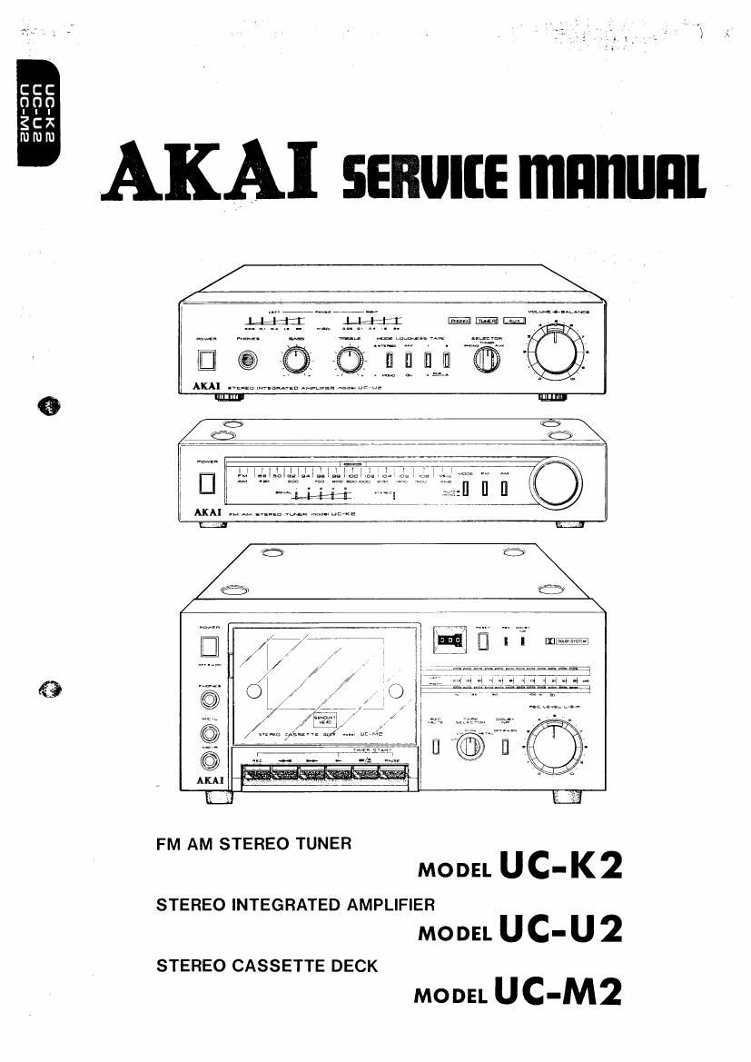
This is the 93 pages manual for Akai UCK 2 Service Manual.
Read or download the pdf for free.
If you want to contribute, please mail your pdfs to info@audioservicemanuals.com.
FM AM STEREO TUNER
MO DEL U c " K 2
STEREO INTEGRATED AMPLIFIER
MODEL UC-U 2
MODEL UC-M2
STEREO CASSETTE DECK
FM AM STEREO TUNER
MODEL [JG-[(2
STEREO INTEGRATED AMPLIFIER
MODEL UC-U2
STEREO CA SSETTE DECK
MODEL UC-MZ
ALSO APPLICABLE TO BLACK PANEL MODEL
TAB LE OF CONTENTS
SECTION 1 MODEL UC-KZ ........................ 3
SECTION 2 MODEL UC-U2 ........................ [5
SECTION 3 MODEL UC-M2 ........................ 29
SECTION 4 PARTS LIST .......................... 47
SECTION 5 SCHEMATIC DIAGRAM ................ 78
Adjustment Adjustment
Step Item Point Result Remarks
Selector to AM. 600 kHz, 34 dB from
1 IF Amp Gain R107 (1 k) 50 mV (OUTPUT) ssc to TPl input.
Modulation: 1 kHz, 30%
530 kHz 50 dB input.
2 L°w R1"? scale T103 (RED) Maximum Ontput Scale indicator to 530 kHz.
Indication . .
Error: wrthm 2%
3 Low Range T1130: $231: ) Mfimmumnggtuogién 530 kHz 50 dB input.
Sensitivity a . n m Less than 10% Distortion Factor
C011 Factor
. 1600 kHz 50 dB input.
4 High Range Scale C60 Maximum Output Scale indicator to 1600 kHz.
Indication (Front End) . .
Error: w1thm 2%
5 High Range 059 MM?T""B::J§:II 1600 kHz 50 dB input.
Sensitivity (Front End) mm 111 Less than 10% Distortion Factor
Factor
1. Detune, then tum R516 (50 k) and temporarily light Signal
LED 1.
6 Slgna-l LED R516 (50 k) 2. Tum R516 (50 k) m counterclockwrse d1rect10n until LED l
Sensmvrty goes out,
3. Input 1000 kHz, 90 to 120 dB from the AM ANT terminal
and check that signal LED 4.
NOTE: For the best results, repeat Steps 1 through 5 two or three times.
Chart-2