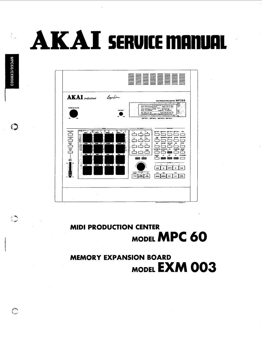
Akai MPC 60 Service Manual

This is the 65 pages manual for Akai MPC 60 Service Manual.
Read or download the pdf for free. If you want to contribute, please mail your pdfs to info@audioservicemanuals.com.

Page: 1 / 65
left right
Akai MPC 60 Service Manual

Extracted text from Akai MPC 60 Service Manual (Ocr-read)


Page 2

PRECAUTIONS DURING SERVIDING

l, Pans identified by the [5 symbols are critical for safety.
Replace only with pans number specified.

2. In addition to safety, other parts and assemblies are
specified for conformance with such regulations as those
applying to spurious radiation.

These must also be replaced only with specified
replacements.

Examples: RF converters, tuner units, antenna selector
switches, RF cables, noise blocking capacitors, noise
blocking filters, etc.

3. Use specified internal wiring. Note especially:

1) Wires covered with PVC tubing
2) Double insulated wires
3) High voltage leads

4-. Use specified insulating materials for hazardous live parts.

Note. especially:

1) Insulation Tape

2) PVC tubing

3) Spacers (Insulating Barriers)

4) Insulation sheets for transistors

5) Plastic screws for fixing microswitch (especially in
turntable) '

5. When replacing AC primary side components (transform-
ers, power cords, noise blocking capacitors, etc), wrap
ends of wires securely about the terminals before soldering

assist

6. Observe that wires do not contact heat producing parts
(heatsinks, oxide metal film resistors, fusible resistors,
etc.).

* INFORMATION

SYMBOLS FOR PRIMARY DESTINATION
Alphabet indicates the destination of the units as listed below.

Symbols Principal Destinations

USA

UK

Canada

Europe (except UK)

Japan

Australia

W. Germany only

Universal Area

Custom version

SERVICE MANUAL

7. Check that replaced wires do not contact sharp edged or
pointed parts.

8. Also check areas surrounding repaired locations

9. Use care that foreign objects (screws, solder droplets, etc.)
do not remain inside the set.

SAFETY CHECK AFTER SERVICING

Confirm the specified insulation resistance between power
cord plug prongs and externally exposed pans of the set is
greater than 10 M ohms, but for equipment with external
antenna terminals (tuner, receiver, etc.) and is intended for
or , specified insulation resistance should be head-
phone jacks, line-in-out jacks, etc. more than 2.2 M ohms
(ground terminals, microphone jacks).

PRECAUTIONS FOR LITHIUM BATTERY

The lithium battery may explode when heated excessively
[OBSERVE THE FOLLOWING WHEN REPLACING]
0 Replace with the same make and type only.

0 Use soldering iron in "recommended way" only.

0 Place battery in correct polarity.

0 Do not short the terminals.

0 Do not recharge battery.

0 Do not dispose of battery in fire.

[DANGER] [RECOMMENDED WAY]

VOLTAGE CONVERSION
( V E B S Model only)

Before connecting the power cord, set the VOLTAGE
SELECTOR located on the bottom plate with a screw-driver
so that the correct voltage is indicated.

VOLTAGE
SELECTOR

220v [11:] 240v

.L.

Page 9

5-1. Adjustment of A/ D converter OFF-SET

(ADC PCB)

1. Select "2) ADC Monitor" by pressing the DATA ENTRY

key, Then the LC-display will change as shown below
indicating that the unit enters the OFF-SET adjustment
mode. (Refer to Fig. 5-3).

3. Connect the oscilloscope to terminal of ASSIGN-

m located on the rear panel. (The
attenuation level can be altered in 6dB steps with the
DATA CONTROL dial. The adjustment range is between
36dB and 48dB.)

It notches appear in thel waveform displayed on the

oscilloscope as shown Fig. 5-6, adjust VRl on the VOICE
PCB as shown Fig. 5-7.

ADC Monitor =

ADC Value = 0008

(Press ENTER to return to main menu)

Fig. 5.3

2. Set the indicated ADC-value between 0003 and 000E by
adjusting VR2 on the ADC PCB.

3. Press the ENTER key when the adjustment is completed.

5-2. D/A converter MSB-adjustment (VOICE PCB)

1. Select 1) DAC Trim (15 Hz out #8) by pressing the
DATA ENTRY key. The LC-display will change as
shown below, indicating that the sine wave for MSB
adjustment is being loaded. (Refer to Fig. 5-4)

Fig. 5-7

== DAC Trim =

5-3. Adjustment of D/A converter OFF-SET
(VOICE PCB)
1. At first, switch the MCP60 OFF to terminate the test
mode. Then switch power ON again, and load the data
of the DRUM SOUND DATA STUDIO-SET" (Stan-
dard accessoriesjin DISK mode.

Loading sine wave into sound memory...

0000:0000

Fig. 5.4 2. Press the FULL LEVEL" key on the left of the front
panel to set the unit to FULL LEVEL mode. Press the
BASS DRUM" pad and adjust each VR so that there
is no click noise during sustain. The outputs and their
corresponding VRs are as follows.

2. Then the following screen will appear to indicate that the
sine wave has been loaded and the M38 adjustment mode
is set. (Refer to Fig. 5-5)

ASSIGNABLE MIX OUT 1 ..
MIX OUT .........................
STEREO OUT RIGHT CH
STEREO OUT LEFT CH....

== DAC Trim =

15 Hz signal preset: at Output #8

Note: Connect the corresponding output of the MCPGO
to an amplifier and adjust each VR according to the
sound coming out of the speaker.

Attenuation: 42 db

(Press ENTER to return to main menu)

Fig. 5-5

SERVICE MANUAL

Page 15

VII. PARTS LIST

HOW TO USE THIS PARTSlLIST

1. This Parts List lists those parts which are considered necessary for repairs Other common parts, such as resistors and
capacitors, are listed in the Common List for Service Parts" from which these parts should be selected and stocked
2. The Recommended Spare Parts List shows those parts in the Parts List which are considered particularly important

for service.

3. Parts not shown in the Parts List and Common List for Service Parts will not in principle be supplied.
4. How to read the Parts List, ,
a) Mechanism Block b) PC Board
2. HEAD BASE BLOCK . 6. MAIN PC BOARD
fig PART NO. DESCRIPTION :3 PART No. DESCRIPTION
2-1): BH-T202 3A320A HEAD BASE BLOCK s-rcr El-324536 IC HD14049BP
2~2 HH-izzosAoloA HEAD R/P PR4-8FU c are: EI-336801 rc M38841-564M
2»3 25477376 PANzoxoasTL CMT 6-ClA 50333399 C MMY v 223M zsoAc [U,E,B,S]
2-4 zs-sas4ss BinzoxosSTL CMT ecu; lac-350949 C MMY v 223M1250DC [I]
25 26-402895 SP cs ANGLE ADJUST s-Crc lac-333397 c MMY v 223M 125AC [C,A]

a-xr EI-313354 osc XTAL NC-isc :1-

Symbols for primary destination
[A]:AAL(U.S.A.) [S]:SAA(Australia)
[B] : BEAB(England) [U] : U/T(Universal Area)
[C]:CSA(Canada) [V] : VDE(W. Germany)
[B] : CEE (Europe) [Y] : Custom Version
IJIZJPNUapan)

This number corresponds with the Figure SP (Service Parts) Classification

Number. These reference symbols correspond with
component symbols in the Schematic
Diagrams.

SP (Service Parts) Classification

A small x" indicates that this part is not
shown in the Photo or Illustration.

This number corresponds with the indi-
vidual parts index number in that figure,

The available PC Board Blocks are listed separately.
5, When Part No. is known, Parts Index at end of Parts List can be used to locate where that part is shown in Parts List

by its Reference No. listed at right of Part No.

PARTS LIST

17