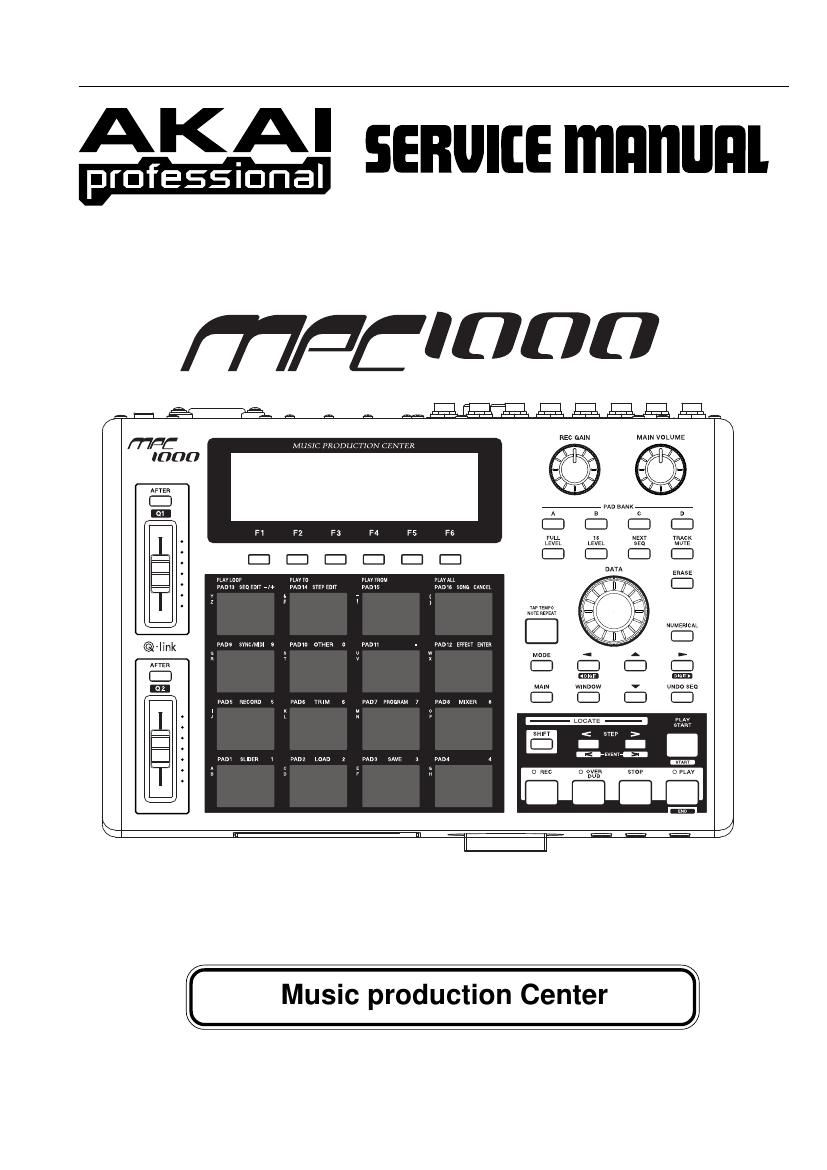
Akai MPC 1000 Service Manual

This is the 22 pages manual for Akai MPC 1000 Service Manual.
Read or download the pdf for free. If you want to contribute, please mail your pdfs to info@audioservicemanuals.com.

Page: 1 / 22
left right
Akai MPC 1000 Service Manual

Extracted text from Akai MPC 1000 Service Manual (Ocr-read)


Page 1

SER VICE MANUAL 2 SAFETY INSTRUCTIONS INFORMA TIONS 1. Parts identified by the  symbol are critical for safety . Replace them only with the parts number specified. 2.In addition to safety , other parts and assemblies are specified for conformance with such regulations as those applying to spurious radiation. These must also be replaced only with the specified replacements. Examples :Noise blocking capacitors, noise blocking filters, etc. 3. Use specified internal wiring. Note especially : 1) Wires covered with PVC tubing 2) Double insulated wires 3) High voltage leads 4. Use specified insulating materials for hazardous live parts. Note especially : 1) Insulation T ape 2) PVC tubing 3) Spacers (insulating barriers) 4) Insulation sheets for transistors 5) Plastic screws for fixing micro switches 5.When replacing AC primary side components (trans- formers, power cords, noise blocking capacitors, etc.), wrap the ends of the wires securely around the terminals before soldering. 6. Make sure that wires do not contact heat producing parts (heat sinks, oxide metal film resistors, fusible resistors, etc.). 7.Check that replaced wires do not contact sharp edged or pointed parts. 8. Also check areas surrounding repaired locations. 9.Make sure that foreign objects (screws, solder droplets, etc.) do not remain inside the set. SAFETY CHECK AFTER SER VICING After servicing, make measurements of leakage-current or resistance in order to determine that exposed parts are acceptably insulated from the supply circuit. The leakage- current measurement should be done between accessible metal parts (such as chassis, ground terminal, microphone jacks, signal input/output connectors, etc.) and the earth ground through a resistor of 1500 ohms paralleled with a 0.15 F capacitor , under the unit s normal working conditions. The leakage-current should be less than 0.5 mA rms AC. The resistance measurement should be done between accessible exposed metal parts and power cord plug prongs with the power switch (if included) ON . The resistance should be more than 2.2 M ohms. SYMBOLS FOR PRIMAR Y DESTINA TION Unit destinations are indicated with letters as shown below . Symbols Principal Destinations A U.S.A B England E Europe J Japan V Germany X1 Japan X4 Universal Area MAKE YOUR CONTRIBUTION TO PROTECT THEENVIRONMENT Used batteries with the ISO symbol for recycling as well as small accumulators (rechargeable batteries), mini-batteries (cells) and starter batteries should not be thrown into the garbage can. Please leave them at an appropriate depot. PRECAUTIONS FOR LITHIUM BATTERY The lithium battery may explode when incorrectly replaced. [OBSERVE THE FOLLOEING WHEN REPLACING] Replace with the same make and type or equivalent recom mended by manufacturer. Place battery in correct polarity. Do not short the terminals. Do not charge battery. Do not dispose of battery in fire.

Page 2

SER VICE MANUAL 3 * The specifications are subject to change without the prior notice. I. SPECIFICA TIONS General Display 240 x 64 dot graphic LCD w/back light Memory card slot Compact Flash (The size of the compact flash card the MPC1000 can handle is from 32MB to 2GB) Dimentions (W x H x D) 330 x 75.5 x 228.2(Max 234.6) Weight 3.45kg Power reqirement 19W Sound generator Sampling rate 44.1kHz Memory capacity 16MB standard (11.5MB for sound memory), expandable to 128MB Recording time 136sec. (16MB, MONO), 24m28sec. (128MB, MONO) Memory expansion slot 1 x for optional EXM128 Data format 16-bit linear Polyphony 32 Dynamic filtering 2 x 2-pole filter per voice Filter type Low pass, Band pass, High pass Preset sound memory 5MB Number of programs 24 Effects Effects 2 stereo effects and Master effect Effect type Chorus, Flanger, Bit grunger, 4 band EQ, Compressor, Phase shifter, Tremolo, Flying pan, Reverb Master effect: 4 band EQ, Compressor Sequencer Maximum events 100,000 notes Resolution 96 parts per 1/4-note Sequences 99 Tracks per sequence 64 MIDI output channels 32 (16 channels x 2 outputs) Song mode 20 songs, 250 steps per song Drum pad 16 (velocity and pressure sensitive) Drum pad banks 4 Sync mode MIDI clock

Page 8

SER VICE MANUAL 9 V. PARTS LIST HOW TO USE THIS PARTS LIST 1. This Parts List lists those parts which are considered necessary for rep\ airs. 2. Parts not shown in the Parts List will not in principle be supplied. 3. How to read the Parts List. WARNING  INDICATES SAFETY CRITICAL COMPONENTS. FOR CONTINUED SAFETY, REPLACE SAF\ ETY CRITICAL COMPONENTS ONLY WITH MANUFACTURER'S RECOMMENDED PARTS. AVERTISSEMENT  IL INDIQUE LES COMPOSANTS CRITIQUES DE SÉCURIT É. POUR MAINTENIR LE DEGR É DE S ÉCURIT ÉDE L'APPAREIL, NE REMPLACER QUE DES PI ÉCES RECOMMANDEES PAR L É FABRICANT. 1. PC MAIN BOARD BLK Ref. No. Part No. Description D5 ED-431276C D SCHOT 1S30-J T05 D110 ED-431276C D SCHOT 1S30-J T05 : : IC5 EI-81 1073J ICTRC-6593 IC10 EI-81 1068J IC HD74HC157FP Service parts classification These reference symbols correspond with component symbols in the Schematic Diagrams. 2. FINAL ASSEMBL Y BLK Ref. No. Part No. Description 1. SA-349332 FOOT 2. ZS-344754C ST PAN30x06STL CMT : : 44. SP-417333J COVER T OP 45. ZS-418385J BT BID30X06STL BNI EA TRH LOCK 46-A  EW -380905J AC CORD 250S KP300 KS16A H B J [J] 46-B  EW -368420J1 AC CORD 200SKP30KS B AC [A] 46-C  EW -410608J AC CORD 250 KP4819D KS31A B E [E,V ] Symbols for primary destination [A] U.S.A. [J] Japan [B] England [V] Germany [E] Europe [x1] Japan [X4] Universal Area Safety critical component This number corresponds with the individual parts index number in the figure. ATTENTION 1. When placing an order for parts, be sure to list the Part No., Model No.\ and the description of each part. Otherwise, the non-delivery of the part or the delivery of a wrong part \ may result. 2. Please make sure that Part No. is correct when ordering. If not, a part different from the one you ordered may be delivered. 3. Since the parts shown in Parts List or Preliminary Service Manual may ha\ ve been the subject of changes, please use this Parts List for all future reference.

Page 15

FOOT SW PC (#)MAIN (FRONT) HEAD PHONE PC (#) OPERA TION (OPERATION - F)