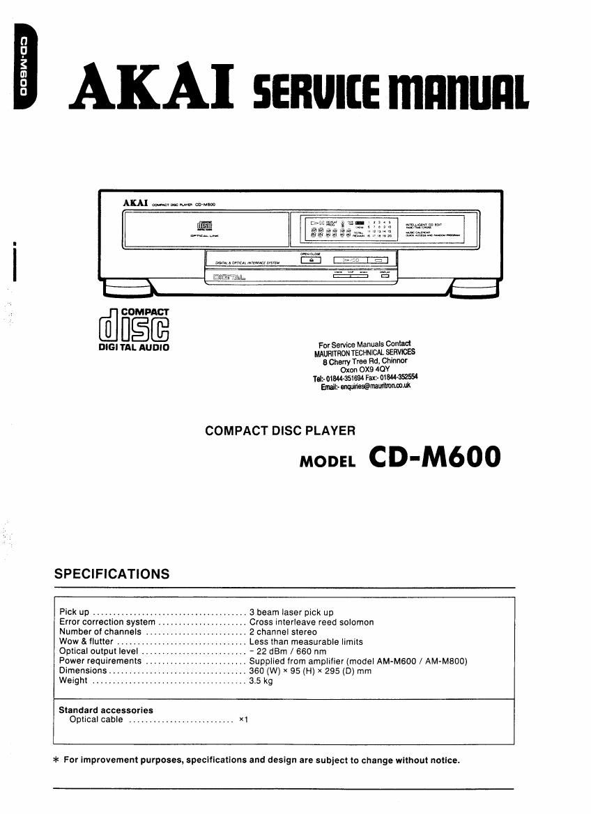
Akai M 600 Service Manual

This is the 39 pages manual for Akai M 600 Service Manual.
Read or download the pdf for free. If you want to contribute, please mail your pdfs to info@audioservicemanuals.com.

Page: 1 / 39
left right
Akai M 600 Service Manual

Extracted text from Akai M 600 Service Manual (Ocr-read)


Page 1

OOBW'UD

AKA] senurre mnnunl


AKAI minnow co-ch

wmmm m an
weaves

>4me
we. nun Wm...

mam 0mm memes 5mm

@flEirr'AlL

D'G' TAL AUDIO MAURII'RON TECHNICAL SERVICES
8 Cherry Tree Rd. Chinnor
Oxon 0X9 4OY
Tell-01944651694 Fax:- 01344-352554

Emall:- enquiries@mau1ilmnm.uk

For Service Manuals Contact

COMPACT DISC PLAYER

MODEL CD-M600

SPECIFICATIONS

...l abeam laser pick up
.. Cross interleave reed solomon
.. 2 channel stereo
.. Less than measurable limits
.. '22dBm/660nm
.. Supplied from amplifier (model AM-M600 / AM-MBOO)
360 (W) x 95 (H) x 295 (D) mm

Pick up .................
Error correction system .
Number of channels ..
Wow & flutter .........
Optical output level .....
Power requirements

Dimensions ........... .
Weight ...................... . 3.5 kg
Standard accessories

Optical cable .......................... X1

>l< For improvement purposes, specifications and design are subject to change without notice.

Page 2

* SAFETY INSTRUCTIONS

PRECAUTIONS DURING SERVICING

1, Parts identified by the /L\ (*) symbol are critical for
safety Replace only with pans number specified.

2. in addition to safety, other parts and assemblies are
specified for conformance with such regulations as
those applying to spurious radiationt
These must also be replaced only with specified re-
placements
Examples: RF converters, tuner units, antenna selector
switches, FtF cables, noise blocking capacitors, noise
blocking filters, etc,

3 Use specified internal wiring. Note especially:

1) Wires covered with PVC tubing
2) Double insulated wires
3) High voltage leads

4, Use specified insulating materials for hazardous live

parts. Note especially:

1) Insulation Tape

2) PVC tubing

3) Spacers (Insulating Barriers)

4) insulation sheets for transistors

5) Plastic screws for fixing microswitch (especially in
turntable)

5. When replacing AC primary side components (trans-
formers, power cords, noise blocking capacitors, etc),
wrap ends of wires securely about the terminals before
soldering.

semiarid?

6, Observe that wires do not contact heat producing parts
(heatsinks, oxide metal film resistors. fusible resistors,
etc).

SERVICE MANUAL

7. Check that replaced wires do not contact sharp edged
or pointed parts.

8. Also check areas surrounding repaired locations.

9. Use care that foreign objects (screws, solder droplets,
etc) do not remain inside the set.

Page 12

995!

AKAI

mom CD-MbOO

SCHEMATIC DIAGRAMS
AND PC BOARDS

TABLE OF CONTENTS

BLOCK DIAGRAM .................................................................
SCHEMATIC DIAGRAM ............................................................
MAIN AND OTHER PC BOARDS ..................................................
INFORMATION 0F ICs ............................................................

For Service Manuals Contact
MAURITRON TECHNICAL SERVICES
8 Cherry Tree Rd, Chinnor
Oxon OX9 4QY
Tet- ozmasteaa Faxz- 01644-352554
Email:- muesebmaummnmuk