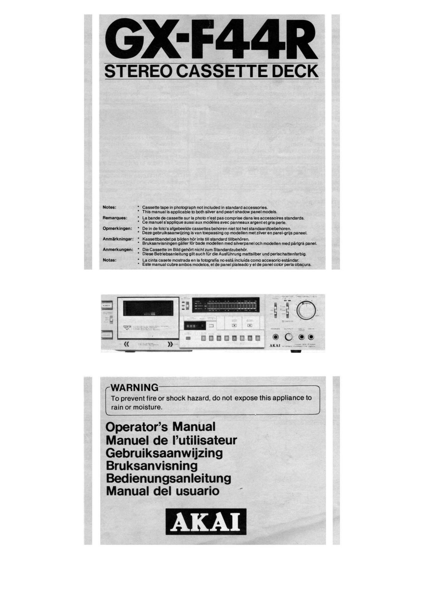
Akai GXF 44 R Owners Manual

This is the 64 pages manual for Akai GXF 44 R Owners Manual.
Read or download the pdf for free. If you want to contribute, please mail your pdfs to info@audioservicemanuals.com.

Page: 1 / 64
left right
Akai GXF 44 R Owners Manual

Extracted text from Akai GXF 44 R Owners Manual (Ocr-read)


Page 1

GX-F44R

STEREO CASSETTE DECK

Notes:

Remarques :

Opmerklngen:

Anmerkungen:

Notes:

WARNING

To prevent fire or shock hazard. do not expose this appliance to
rain or moisture.

' Cassette tape in photograph not Included in standard accessories.
' This manual is applicable to both silver and pearl shadow panel models.

' La bands de cassette sur la photo n'est pas comprise dans les accessolres standards.
' Ce manuel sappllque aussi aux modeles avec panneaux argent et aria perle.

' De In de toto's algebeelde cassettes behoren nlet tot het standaardtoebehoren.

' Dene oebrulkaaanwijzlng is van toepasslng op modellen met zllver en parekgrlis paneel.
Anmlrkningsr: '
' Bruksanvisningen pillar for bade modellen med sllverpanel och modellen med parlors panel.

Kassettbandetpa bllden h6r lnte tlll standard tlilbehéren.

' Die Cassette im Bild cohort nicht zum Standardzubel'ior.
' Dlese Betriebsenleitung gilt auch lur die Austfihrung mattsllber und perlsc hattenlarblg.

' La clnta casete mostrada en la lotografia no esta lncluida como accesorlo eaténdar.
' Este manual cubre ambos modelos. el de panel plateado y el de panel color perla obscure.

DDUDDEEB © 0 (so

Operators Manual

Manuel de lutilisateur
Gebruiksaanwijzing
Bruksanvisning
Bedienungsanleitung
Manual del usuario

Page 2

WARNING

POWER REQUIREMENTS

Power requirements for electrical equipment differ from area to area.
Please ensure that your machine meets the power requirements in your
area.

If in doubt. consult a qualified electrician.

1 20V, 60 Hz for USA and Canada

220V, 50 Hz for Europe except UK

240V. 50 Hz for UK and Australia

1 10V/120V/220V/240V, 50/60 Hz internally switchable for other coun-
tries.

VOLTAGE CONVERSION

Do Not Attempt This Conversion Yourself.

Voltage conversion (Models for Canada, USA. Europe, UK and Australia

are not equipped with this facility) Each machine is preset at the factory

according to destination, but some machines can be set to 110V. 120V,

220V or 240V as required. If your machine's voltage can be converted.

refer the following voltage conversion to a qualified Service Repair

Shop or professional service personnel.

1. Disconnect powercord.

2. Loosen holding screws of the top panel and the two top screws of
the rear panel and remove top panel.

3. Remove short pin plug from present holes and replace in correct
holes. Follow the markings explicitly.

\

Power Transformer

Rear Panel \

IQ rnovz-V AOZL -.

©0000

x-zzov-A-uov-J

[:9

Short Pin
This equipment confirms to No. 76-889 EEC standard.

DEW FORMATION

Dew is the term used for the formation of moisture on the very important
transport section such as the head and the capstan when the deck is
used in places where humidity is high. subjected to sudden changes
in temperature or moved from a cold place to a warm one. If
the deck is used when dew is present, the tape will stick to the head
and be ruined or tape will not be transport properly. In such cases. do
not use the'deck for approximately one hour until the deck is acclima-
tized.

PRECAUTIONS

CAUTION

RISK OF ELECTRIC SHOCK
DO NOT OPEN

CAUTION: TO REDUCE THE RISK OF ELECTRIC
SHOCK, DO NOT REMOVE COVER (OR
BACK).

NO USER-SERVICEABLE PARTS INSIDE.

REFER SERVICING TO QUALIFIED SERVICE

PERSONNEL.

10.

11.

12.
13.

The lightning flash with arrowhead symbol superimposed
' across a graphical representation of a person. within an equi-
lateral triangle, is intended to alert the user of the presence of
° uninsulated dangerous voltage" within the prod ucts enclo-
sure; that may be of sufficient magnitude to constitute a risk
of electric shock to persons.
. The exclamation point within an equilateral triangle is intend-
ed to alert the user of the presence of important operating
. and maintenance (servicing) instructions in the literature ac-
companying the appliance.

Use only household AC power sources.

Never use DC power sources.

Always set the amplifiers volume control to minimum when turning
on or off the deck.

Touching the plug with wet hands risks dangerous electric shocks.

Always pull out by the plug and never the cord.

Make sure the power consumption to each audio component
does no exceed wattage specified.

Only connect other audio components.

Only let a qualified professional repair or reassemble the equip-
ment. An unauthorized person may touch the internal parts and re-
ceive a serious electric shock.

Never allow a child to put anything, especially metal into this
equipment. A serious shock or malfunction may occur.

if water is spilled on this equipment, disconnect and call your
dealer.

Make sure the equipment is well ventilated and away from direct
sunlight.

Keep away from heat (stoves, etc.) to avoid damage to the external
surface and internal circuits.

Avoid spray-type insecticides which will damage the equipment
and may ignite suddenly.

To avoid damaging the finish never use alcohol. paint thinner or
others similar chemicals.

Always place the equipmenton a flat and solid surface.

Please read this manual in its entirety and keep it handy for further
reference.

Page 13

TROUBLE SHOOTING

The conditions listed below do not indicate mechanical failure of your
unit. If your machine exhibits any of these conditions. check for trouble
as indicated.

Recording button will not function

* Cassette is not loaded.

* Cassette breakout tabs are removed. Plug or cover cavities.

Tape will not run

* Power is not being supplied. Check power cord and POWER switch.
Tape slack. Take up slack as mentioned in "Cassette Tape Care.
Noisy Sound

* Heads are dirty. Clean following head cleaning instructions.

Heads are magnetized. Demagnetize following head demagnetizing
instructions.

Previous recording will not erase

' Erase head dirty. Clean following head cleaning instructions.
Distorted sound

Recording level is too high. Use as explained under Recording.
Playback cannot be effected

* Connections are incorrect.

Controls are not properly adjusted or positioned.

Check external amplifier controls.

* PAUSE ( ll ) button is depressed.

O

t

*

Recording will not take place
Dirty head. Clean following head cleaning instructions.
* Connections are incorrect.
* Controls are not properly positioned or adjusted.
Check external source controls.
*. PAUSE ( ll ) button is depressed.
The correct indicator will not light when chrome tape is loaded
* Old cassette used. Use a new cassette with notches for triggering
chrome position.
Quick reverse will not take place
REV SELECTOR not set to proper position. Set to :3 ore-:3.
* No leader tape sections or leader tape sections not clear enough.
Use tape with leader tape sections or with clear leader tape
sections.
Sensor head dirty. Clean the sensor head.
Tape stop durin 9 fast forward or rewind
* MEMORY switch set to ON. Set to OFF.

t

Should there be a problem with your machine. write down the model
and serial numbers and all pertinent data regarding warranty coverage
as well as a clear description of the existing trouble and contact your
nearest authorized Akai Service Station or the Service Department of
Akai Company, Tokyo. Japan.

SPECIFICATIONS

Track System ............... 4 Track 2 Channel Stereo System Input ......................... MIC: 0.25 mV (input impedance
Tape ....................... '. . Philips Type Cassette 5.0 kohms)
Tape Speed ................. 4.76 cm/s 1- 1.5% (1 -7/8 ips. :1.5%) Required microphone impedance:
Heads ....................... Twin Field Super GX head for 600 ohms
recording/playback x 1 Line: 70 mV (input impedance 47
Erase head X 2 kohms)
Motors ....................... Electronically speed controlled Output ....................... Line: 410 mv at 0 VU
DC. motor for capstan drive x 1 Required load impedance: more than
DC. motor for reel drive x 1 20 kohms
Wow & Flutter ............... Less than 0.035% WRMS. 0.1 1% Phone: 1.3 mW/B ohms at 0 VU
(DIN 45 500) DIN .......................... Input: 2.0 mV (input impedance
Tape Winding Time ......... 80 sec. using a C-60 cassette tape 10 kohms)
Frequency Response ....... Normal: 25 to 16,000 Hz: 3 dB Output: 410 mV
(- 20 VU) Required load impedance: more than
CrOz: 25 to 17,000 Hz: 3 dB 20 kohms
(-20 VU) Power Requirements ........ 120V, 60 Hz for USA and Canada
25 to 9.000 H213 dB 220V, 50 Hz for Europe except UK
(0 VU) 240V, 50 Hz for UK and Australia
Metal: 25 to 19.000 Hz: 3 dB 1 10V/1 20V/220V/240V. 50/60 Hz
(- 20 VU) switchable for other countries
25 to 13,000 Hz: 3 dB Dimensions .................. 440(W) X 118(H) X 309(D)mm
(0 VU) (17.3x4.7x12.2")
Signal to Noise Ratio ........ Normal: Better than 58 dB Weight ....................... 8.6 kg (19.0 lbs)
CrOZ: Better than 60 dB
Metal: Better than 60 dB STANDARD ACCESSORIES
(measured via tape with peak recording Connection Cords ............................................... 1 set
_ level) . Operator's Manual .................................................. 1
Dolby 8 NR ON: improves up to 5 dB at i
1 kHz, 10 dB above 5 kHz . * For improvement purposes. specifications and design are subject to
Dolby C NR ON. improves up to 15 dB at g change without notice.

500 Hz. 20 dB at 1 to 10 kHz' " "Dolby" and the Double D symbol are trademarks of Dolby
Harmonic Distortion ........ Normal: Less than 0.8% . Laboratories.
CrOZ: Less than 0.7% . (Manufactured under license from Dolby Laboratories).
Metal: Less than 0.7% i

12