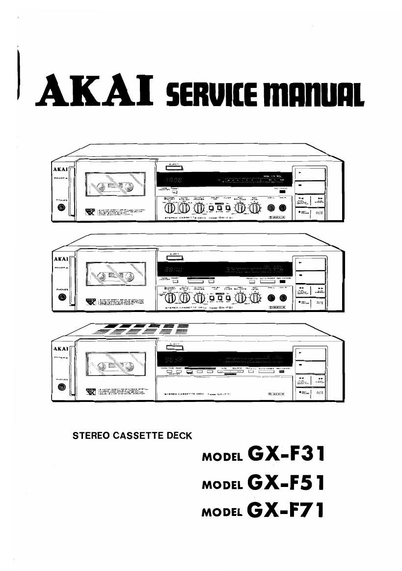
Akai GXF 31 Service Manual

This is the 133 pages manual for Akai GXF 31 Service Manual.
Read or download the pdf for free. If you want to contribute, please mail your pdfs to info@audioservicemanuals.com.

Page: 1 / 133
left right
Akai GXF 31 Service Manual

Extracted text from Akai GXF 31 Service Manual (Ocr-read)


Page 5

SECTION 1

CIRCUIT OPERATION DESCRIPTION

TABLE OF CONTENTS

.<

DESCRIPTION OF GX-F71 AUTO TUNING FUNCTION ............ l- 2
l. GX-F71 AUTO TUNING BLOCK DIAGRAM ................... 1- 2
2. DESCRIPTION OF GX-F7l AUTO TUNING FUNCTION .......... 1. 3
3. INPUT OUTPUT MODES OF EACH TERMINAL 0F
AUTO TUNING CPU (M58841-600I) ......... 1- 4
GX-F7l SYSCON CIRCUIT FUNCTIONS ....................... l- 5
l. GX-F7l SYSCON BLOCK DIAGRAM ....................... 1- 5
2, MEANING EACH TERMINAL 0F CPU (LM6402 H063) ........... l- 6
3. CONNECTION OF EACH TERMINAL 0F IC (LC7800)
FOR EXPANDING GX-F7] INPUT PORT ..... 1- 8
III. DESCRIPTION OF GX~F51 CIRCUIT .......................... l- 9
l, OUTLINE OF GX-FSI AUTO TUNING SYSTEM ................ 1- 9
2. GX-FSI AUTO TUNING BLOCK DIAGRAM .................. 1» 9
3. GX-FS] AUTO TUNING FUNCTION DIAGRAM ................ 1-10
4. GX-FSl PRE AMP BLOCK DIAGRAM ....................... 1-11
IV. AUTO FADER CIRCUIT .................................. 1-12
CAM MOTOR DRIVE CIRCUIT ............................. 1-13
REEL MOTOR DRIVE CIRCUIT ............................. 1-14

VI.

I-l

Page 59

V. VOLTAGE CONVERSION

REAR PANEL

VOLTAGE SELECTOR
VSI
\ l-Aueam- mar
E4) (EDMDQQDRVQ
SHORT PIN

Fig. 4 Voltage Conversion (U Model)

1. VOLTAGE CONVERSION

Models for Canada, Europe, USA, UK, Australia and

Japan are not equipped with this facility.

Each machine is preset at the factory according to

destination, but some machines can be set to 110V,

120V, 220V or 240V as required.

If voltage change is necessary, this can be accom-

plished as follows:

1) Disconnect power cord.

2) Loosen holding screws and remove upper cover.

3) Remove short pin plug from present holes and
replace in correct holes. Follow the markings
explicitly.

2. CYCLE CONVERSION

With DC motor, cycle conversion is not necessary.

4-6