Akai GXC 706 D Service Manual

This is the 18 pages manual for Akai GXC 706 D Service Manual.
Read or download the pdf for free. If you want to contribute, please mail your pdfs to info@audioservicemanuals.com.

Page: 1 / 18
left right
Akai GXC 706 D Service Manual

Extracted text from Akai GXC 706 D Service Manual (Ocr-read)


Page 1

PRELIMINARY SERVICE MANUAL

MODEL GXC-706D DATE May 1978

ewflfié

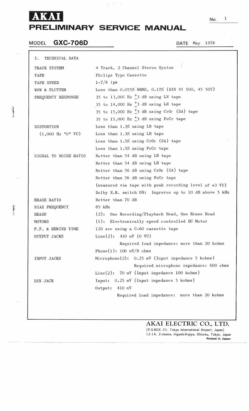
I. TECHNICAL DATA

TRACK SYSTEM

TAPE

TAPE SPEED

WOW & FLUTTER
FREQUENCY RESPONSE

DISTORTION
(1,000 Hz "0" VU)

SIGNAL TO NOISE RATIO

ERASE RATIO
BIAS FREQUENCY
HEADS

MOTORS

F.F. & REWIND TIME
OUTPUT JACKS

INPUT JACKS

DIN JACK

4 Track, 2 Channel Stereo System
Philips Type Cassette
1-7/8 ips
Less than 0.055% WRMS, 0.17% (DIN 45 500, 45 507)
35 to 13,000 Hz i3 dB using LN tape
'55 to 14,000 Hz :3 dB using LH tape
35 to 15,000 Hz fi3 dB using CrO? (SA) tape
35 to 15,000 Hz f3 dB using FeCr tape
Less than 1.3% using LN tape
Less than 1.3% using LH tape
Less than 1.5% using CrOz (SA) tape
Less than 1.5% using FeCr tape
Better than 54 dB using LN tape
Better than 54 dB using LH tape
Better than 56 dB using CrOz (SA) tape
Better than 56 dB using FeCr tape
(measured via tape with peak recording level of +3 VU)
Dolby N.R. switch ON: Improves up to 10 dB above 5 kHz
Better than 70 dB
85 kHz
(2): One Recording/Playback Head, One Erase Head
(1): Electronically speed controlled DC Motor
120 sec using a C-60 cassette tape
Line(2): 410 mV (0 VU)
Required load impedance: more than 20 kohms
Phone(1): 100 mV/S ohms
Microphone(2): 0.25 mV (Input impedance 5 kohms)
Required microphone impedance: 600 ohms
Line(2): 70 mV (Input impedance 100 kohms)
Input: 0.25 mV (Input impedance 5 kohms)
Output: 410 mV
Required load impedance: more than 20 kohms

AKAIELECTRKICOALTD.

(P,0_BOX 21, Tokyo International Airport, Japan)
12-14, 2-chome, Higashi-Kojiya. 0hta»ku, Tokyo. Japan
Printed in Japan

Page 13

MODEL GXC-706D N0. 13

NOTES: 1. Output Level Control should be at maximum.
2. Except for Steps 6 thru 8, set tape selector to Low Noise position.
3. Except for Step 11, set DOLBY N.R. switch to OFF position.

4. USe the following cassette measuring tape:

LN Tape: Fuji FL 0-60
LH Tape: Maxell UD 0-60
CrOzTape: TDK SA 0-60
Fe-Cr Tape: SONY Duad 0-60

5. Stop recording bias oscillator while making Rec Peaking Adjustment
(Refer to Figs. 11,12).

6. If a flat characteristic cannot be obtained from 1,000 Hz to 10,000 Hz
at LH, Cr02 , or Fe-Cr positions, fine adjust at VR8(LH), VR9 (CrOz),
or VRlO (Fe-Cr) respectively.

7. If it does not comply with the specifications, repeat Steps 5 to 9
and re-adjust.

8. Unless the core is moved intentionally this adjustment is not necessary.

9. Because each of these adjustments are Vital to perfect Dolby N.R.
circuit operation, be sure that they are carried out with as little

error as possible.

VI. DC RESISTANCE OF VARIOUS COILS

Parts Designation DC Resistance
Recording/Playback Head P4-36OZ: 370 ohms
Erase Head HF213822A 4.5 ohms

Chart-2