Akai GX 9 Service Manual

This is the 21 pages manual for Akai GX 9 Service Manual.
Read or download the pdf for free. If you want to contribute, please mail your pdfs to info@audioservicemanuals.com.

Page: 1 / 21
left right
Akai GX 9 Service Manual

Extracted text from Akai GX 9 Service Manual (Ocr-read)


Page 1

HPMPPPL

10.
11.

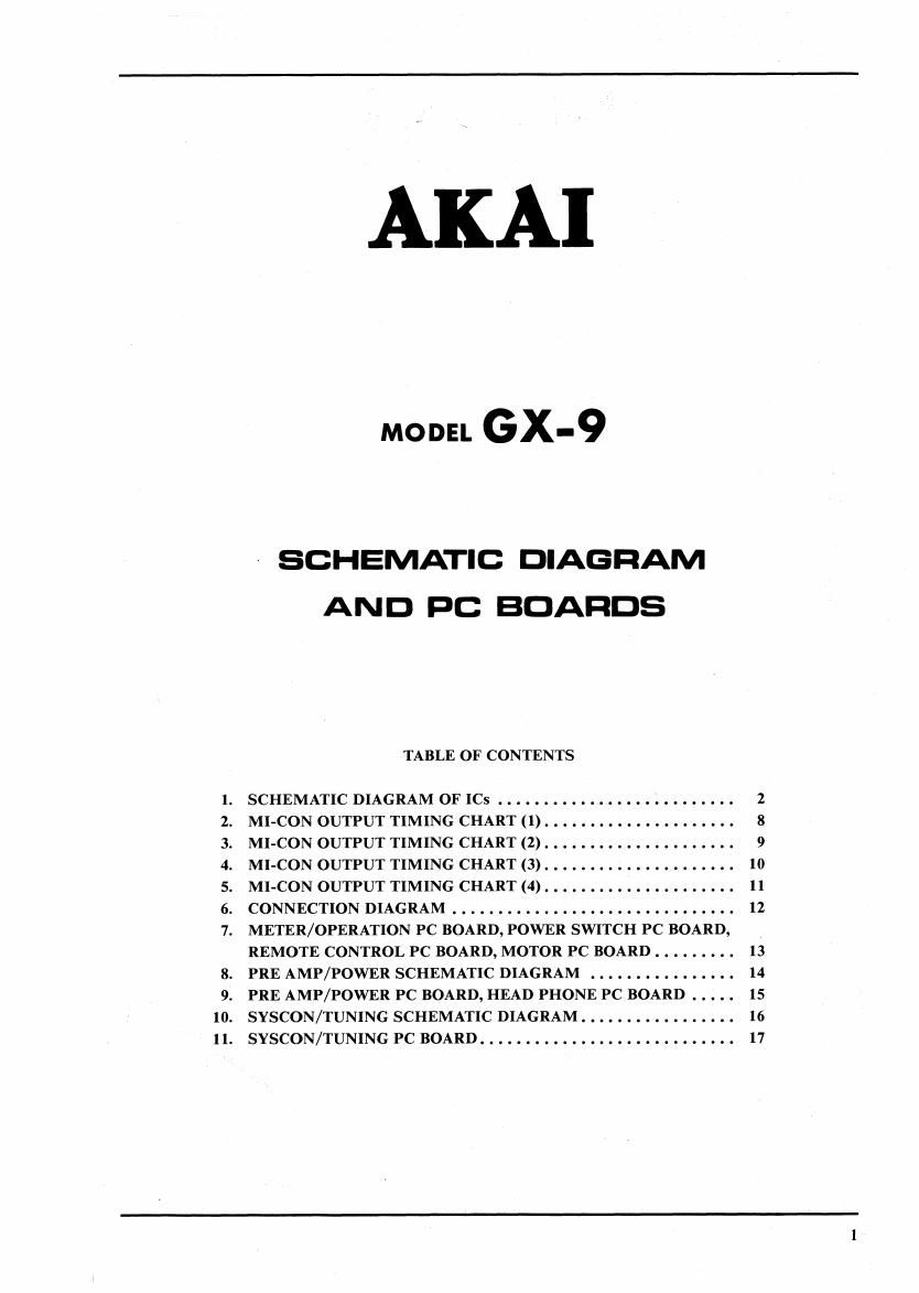
AKA]

MODEL Gx-9

» SCHEMATIC DIAGRAM
AND PC BOARDS

TABLE OF CONTENTS

SCHEMATICDIAGRAMOFICS .......
MI-CON OUTPUT TIMING CHART (1) . . . . . . . . ...... . . . . . . .
MI-CONOUTPUTTIMINGCHART(2).....................
MI-CON OUTPUT TIMING CHART (3). . . . .......... . . . . . . .
MI-CON OUTPUT TIMING CHART (4). . . . . . . . . . . . . . .......
CONNECTIONDIAGRAM.............. ..........
METER/OPERATION PC BOARD, POWER SWITCH PC BOARD,
REMOTE CONTROL PC BOARD, MOTOR PC BOARD . . . . . . . . .
PRE AMP/POWER SCHEMATIC DIAGRAM . . . . . . . . . .......
PRE AMP/POWER PC BOARD, HEAD PHONE PC BOARD . . . . .
SYSCON/TUNING SCHEMATIC DIAGRAM . . . . ...... . . . . . . .
SYSCON/TUNINGPCBOARD.................. ..........

2
8
9
10
11
12

13
14
15
16
17

Page 2

HD6805-XOA29 TERMINALS

PIN PORT NAME DESCRIPTION
1 VSS GND
2 R-ES RESET input
3 W +5V
4 W +sv
5 XTAL
6 EXTAL Oscillator for CLOCK
7 NUM GND
8 TIMER +5V
9 A7 Music interval detect input
10 A6 Not used
11 A5 PLAY PLAY mode
12 A4 STOP STOP mode
13 A3 SEARCH SEARCH mode Comparator reference voltage output for
14 A2 FAST FAST mode CAM MOTOR-
15 A1 FIX FIX (STOP) mode
16 A0 EJECT EJECT mode
17 B7 CSTOP CAM MOTOR rotation finished Signal input
18 B6 REEL (R) REEL MOTOR reverse rotation output
19 B5 REEL (F) REEL MOTOR forward rotation output
20 B4 V3552? Voltage select output for REEL MOTOR
21 B3 SOURCE-M Source mute output (L: mute on, H: mute off)
22 B2 OSC Bias oscillator control output (L: oscillation, H: no oscillation)
23 B1 REC MUTE Mute release output in REC PLAY mode (L: mute on, H: mute off)
24 B0 PB MUTE Mute release output in PB mode (L: mute on, H: mute off)
25 C7 Not used (+5V)
26 C6 LRSS Left (supply) Reel Slit Sensor input
27 C5 RRSS Right (take up) Reel Slit Sensor input
28 C4 DIGIT 4
29 C3 DIGIT 3
30 c2 21:33:Litgiirt§:;:::=;;$°;::;
31 Cl DIGIT 1
32 C0 DIGIT O
33 VCC POWER SUPPLY (+5V)