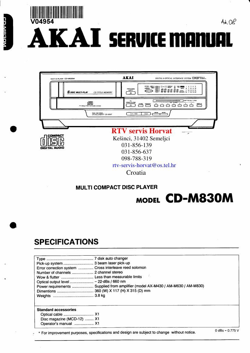
Akai CDM 830 M Service Manual

This is the 37 pages manual for Akai CDM 830 M Service Manual.
Read or download the pdf for free. If you want to contribute, please mail your pdfs to info@audioservicemanuals.com.

Page: 1 / 37
left right
Akai CDM 830 M Service Manual

Extracted text from Akai CDM 830 M Service Manual (Ocr-read)


Page 1

n

H

lllll'll'l'll lllllllllllll _ W
AKA] some mnnunl

w. mush cameo» AKA]

0mm eomcu. INTERFACE synm IIEHTAL.

5 use uummv ca rms MEMORY

@
www-mm,

\ mruuosw cu EDIT

-&&.

\ LI

RTV servis Horvat k.

TBS; Keéinci, 31402 Semeljci
moi-rumour: 031'856'139
031-856-637
098-788-319
rtv-servis-horvat@os.tel.hr
Croatia

MULTI COMPACT DISC PLAYER

moon CD-M83OM

SPECIFICATIONS

Type ..................
Pick-up system ..
Error correction system
Number of channels _
Wow & flutter ........
Optical output level
Power requirements .
Dimentions .
Weights .....

.. 7 disk auto changer

.. 3 beam laser pick-up

.. Cross interleave reed solomon

.. 2 channel stereo

Less than measurable limits

- 22-st I 660 nm

.. Supplied from amplifier (model AX-M430 I AM-M630/ AM-M830)
.. 360 (W) X 117 (H) X 315 (D) mm

.. 3.8 kg


Standard accessories

Optical cable ................... .. X1
Disc magazine (MOD-12) .. X1
Operators manual .................. X1

4 * For improvement purposes, specifications and design are subject to change without notice.

0 st = 0.775 V

Page 2

k SAFETY INSTRUCTIONS

PRECAUTIONS DURING SERVICING

1. Parts indentified by the A (*) symbol are critical for
safety. Replace only with parts number specified.

2. In addition to safety, other pans and assemblies are
specified for conformance with such regulations as those
applying to spurious radiation.

These must also be replaced only with Specified re-
placements.

Examples: RF converters, tuner units, antenna selector
switches, RF cables, noise blocking capacitors, noise
blocking filters, etc.

3. Use specified internal wiring. Note especially:

1) Wires covered with PVC tubing
2) Double insulated wires
3) High voltage leads

4. Use specified insulating materials for hazardous live

parts. Note especially:

1) insulation Tape

2) PVC tubing

3) Spacers (Insulating barriers)

4) Insulation sheets for transistors

5) Plastic screws for fixing microswitch (especially in
turntable)

5. When replacing AC primary side components (trans-
formers, power cords, noise blocking capacitors, etc.),
wrap ends of wires sewrely about the terminals before
soldering.

stats?

6. Observe that wires do not contact heat producing pans
(heatsinks, oxide metal film resistors, fusible resistors,
etc.).

7. Check that replaced wires do not contact sharp edged
or pointed pans.

8. Also check areas surrounding repaired locations.

9. Use care that foreign objects (screws, solder droplets,
etc.) do not remain inside the set.

SERVICE MANUAL

SAFETY CHECK AFTER SERVICING

After servicing, make measurements of leakage-current or
resistance in order to determine that exposed parts are
acceptably insulated from the supply circuit.

The leakage-current measurement should be done be-
tween accessible metal pans (such as chassis, ground
terminal, microphone jacks, signal input/output connec-
tors, etc.) and the earth ground through a resister of 1500
ohms paralleled with a 0.15 pF capacitor, under the units
normal working conditions. The leakage-current should be
less than 0.5 mA nns AC.

The resistance measurement should be done between
accessible exposed metalparts and power cord plug prongs
with the power switch (if included) ON'. The resistance
should be more than 2.2 Mohms.

MAKE YOUR CONTRIBUTION TO PRO-

TECT THE ENVIRONMENT
Used batteries with the ISO symbol for recy-

cling as well as small accumulators (recharge- w .
able batteries), mini-batteries (cells) and %&
starter batteries should not be thrown into

the garbage can.

Please leave them at an appropriate depot. All other house-
hold batteries can be thrown out with the household waste.