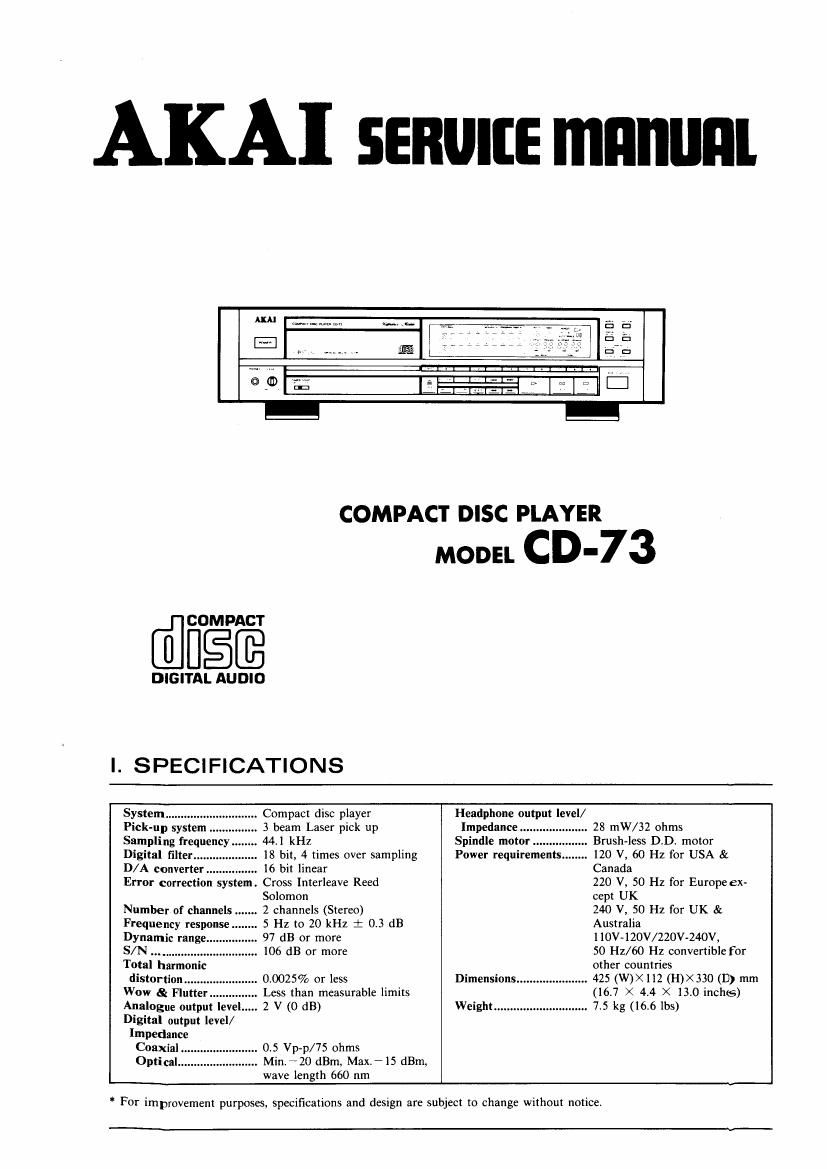
This is the 40 pages manual for Akai CD 73 Service Manual.
Read or download the pdf for free.
If you want to contribute, please mail your pdfs to info@audioservicemanuals.com.
AKA] some mnnuni
COMPACT DISC PLAYER
[flfigfi
DIGITAL AUDIO
I. SPECIFICATIONS
MODEL CD'73
System
Pick-up sys em
Sampling frequency
Digital filter .....
D/A converter.
Error correction system.
Number of channels ..
Frequency response
Dynamic range.
S/N ..............
Total harmon
distortion.
Wow & Flutter
Analogue output level
Digital output level/
Impedance
Coaxial ..
Optical...
. Compact disc player
3 beam Laser pick up
44.1 kHz
18 hit, 4 times over sampling
16 bit linear
Cross Interleave Reed
Solomon
. 2 channels (Stereo)
5 Hz to 20 kHz i 0.3 dB
97 dB or more
. 106 dB or more
. 0.0025% or less
Less than measurable limits
.2V(OdB)
. 0.5 Vp-p/75 ohms
. Min.20 dBm. MaxilS dBm,
wave length 660 nm
Headphone output level/
Impedance... . 28 mW/ 32 ohms
Spindle motor Brush-less D.D. motor
Power requirements . 120 V, 60 Hz for USA &
Canada
220 V, 50 Hz for Europe ex-
cept UK
240 V, 50 Hz for UK &
Australia
110V-l20V/220V-240V,
50 112/60 Hz convertible for
other countries
. 425 (W)><112 (H)><330 (1)) mm
(16.7 X 4.4 X 13.0 inchs)
Weight ............................. 7.5 kg (166 lbs)
Dimensions
For improvement purposes, specifications and design are subject to change without notice.
* SAFETY INSTRUCTIONS
PRECAUTIONS DURING SERVIDING
1. Parts identified by the [5 symbols are critical for safety.
Replace only with pans number specified.
2, In addition to safety, other parts and assemblies are
specified for conformance with such regulations as those
applying to spurious radiation.
These must also be replaced only with specified
replacements
Examples: RF converters, tuner units, antenna selector
switches, RF cables, noise blocking capacitors, noise
blocking filters, etc.
3. Use specified internal wiring. Note especially:
1) Wires covered with PVC tubing
2) Double insulated wires
3) High voltage leads
4. Use specified insulating materials for hazardous live parts.
Note. especially:
1) Insulation Tape
2) PVC tubing
3) Spacers (Insulating Barriers)
4) Insulation sheets for transistors
5) Plastic screws for fixing microswitch (especially in
turntable)
5. When replacing AC primary side components (transform-
ers, power cords, noise blocking capacitors, etc.), wrap
ends of wires securely about the terminals before soldering.
\erénéfl
6. Observe that wires do not contact heat producing parts
(heatsinks, oxide metal film resistors, fusible resistors,
etc.).
* INFORMATION
7. Check that replaced wires do not contact sharp edged or
pointed parts.
8. Also check areas surrounding repaired locations.
9. Use care that foreign objects (screws, solder droplets, etc.)
do not remain inside the set.
SAFETY CHECK AFTER SERVICING
Confirm the specified insulation resistance between power
cord plug prongs and externally exposed parts of the set is
greater than 10 M ohms, but for equipment with external
antenna terminals (tuner, receiver, etc.) and is intended for
or , specified insulation resistance should be head-
phone jacks, line-in-out jacks, etc, more than 2.2 M ohms
(ground terminals, microphone jacks).
BEFORE USING THE CD PLAYER
. s
new mown
On the Transport Locking Lever
This CD player has a Transport Locking Lever located on
the bottom panel. This lever locks the laser pick up
mechanism to prevent vibration during transportation. Make
sure to set this lever to the UNLOCK position before
playback.
Raise the CD player as shown in the illustration (Front panel
facing up), and then turn the Transport Locking Lever to the
UNLOCK position.
When transporting the CD player
Make sure to remove the compact disc from the CD player,
and reset the Transport Locking Lever to the LOCK position.
SYMBOLS FOR PRIMARY DESTINATION
Alphabet indicates the destination of the units as listed below.
Symbols Principal Destinations
USA
UK
Canada
Europe (except UK)
Japan
Australia
W. Germany only
Universal Area
Custom version
SERVICE MANUAL
VOLTAGE CONVERSION Model only)
Before connecting the power cord, SET the VOLTAGE
SELECTOR located on the rear panel with a screwdriver so
that the correct voltage is indicated.
Cl/420V
220v~240v