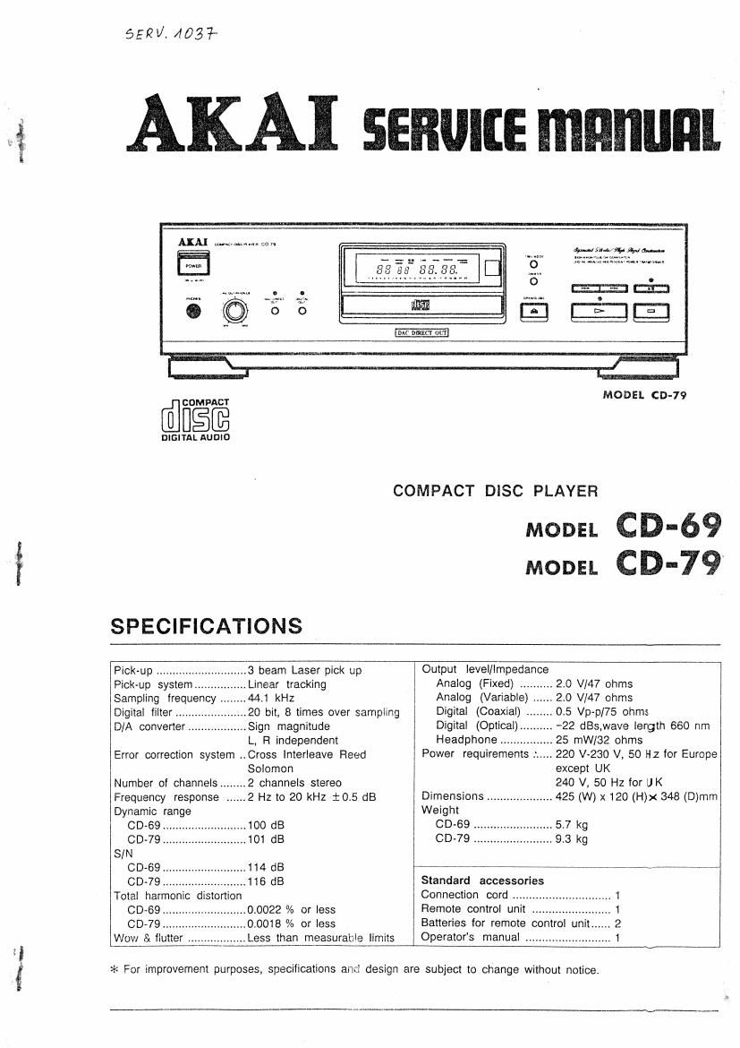
Akai CD 69 Service Manual

This is the 30 pages manual for Akai CD 69 Service Manual.
Read or download the pdf for free. If you want to contribute, please mail your pdfs to info@audioservicemanuals.com.

Page: 1 / 30
left right
Akai CD 69 Service Manual

Extracted text from Akai CD 69 Service Manual (Ocr-read)


Page 1

it
4

5521/1403}

AKAI SEBUIIIE manual

Mr mum on

@IEEiE

DIGIYAL AUDIO

MODEL (ID-79

COMPACT DISC PLAYER

MODEL CD-69
MODEL CD-79

SPECIFICATIONS

Pickup ............................ 3 beam Laser pick up
Pick-up system .......... ...Linear tracking

Sampling frequency.. 44.1 kHz
Digital filter ................ ...20 bit, 8 times over sampling
D/A converter .................. Sign magnitude

L, Ft independent
Error correction system ..Cross lnterleave Reed
Solomon
Number of channels ........ 2 channels stereo
Frequency response ...... 2 Hz to 20 kHz :05 dB
Dynamic range

CD-69 ................ 100 dB
CD-79 ................ 101 dB
S/N
CD-69 .......................... 114 dB
CD-79 .......................... 116 dB
Total harmonic distortion
CD~69 .......................... 00022 % or less
(DD-79 ....... ...0.0018 % or less

Wow & flutter (Less than measurable limits

Output level/impedance
Analog (Fixed) ..
Analog (Variable) .
Digital (Coaxial) ........ 0.5 Vp-p/75 ohms
Digital (Optical)..
Headphone

Power requirementst

25 mW/82 ohms

except UK
240 V, 50 Hz for U K
Dimensions .................... 425 (W) x 120 (H)x 348 (D)mm
Weight
00.69 ..5.7 kg


CD-79 .. .. 9.3 kg

,. -22 st,wave lergth 660 nm

.. 220 V~230 V, 50 Hz for Europe

Standard accessories
Connection cord ..........
Remote control unit .
Batteries for remote control unit ...... 2
Operators manual .......................... 1

>l< For improvement purposes, specifications and design are subject to change without notice.

Page 2

r... .

* SAFETY INSTRUCTIONS

PRECAUTIONS DURING SERVICING

1. Parts indentitied by the .1. (*) symbol are critical lor
salety. Replace them only with the pans number speci-
lied.

. In addition to salety. other parts and assemblies are

specilled tor oonlormarice Wllh suoh regulations as

those applying to spurious radiation,

These must also be replaced only with the specilled ra-

placements.

Examples: FlF converters, tuner units, antenna selec-
tor switches. RF cables. noise blocking ca-
pacitors. noise blocking litters. etc.

Use specified internal wiring, Note especmlly:

t)Wires oovered with PVC tubing

2) Double insulated wires

3) High voltage leads

4 Use specified insulating materials tor hazardous live

parts. Note especially

1) Insulation Tape

2) PVC tubing

3) Spacers ilnsulatirig barriers)

4) Insulation sheets lot transistors

5) Plastic suews tor tlxlng microsztol (especially in
turntaule)

.Wlien replaong AC primary sioe components (trans-

iormers, power oords. noise blocking capacitors. etc).
wrap the ends at the wires securely about the termi-

nals oetore soldering

re

5"

UI

ai

. Make sure that wires do riot contact heat producing
pans (heatsmks. oxide metal Illm resistors. lusible re-
slstors. eta).

.cheok that replaoed wires do not contact sharp edged
or pointed parts.

8 Also check areas surrounding repaired locations.

Make sure that totalng obiects (suews. solder drop~

lets. etc.) do not remain inside the set.

a.

la

- ssnwc: MANUAL

SAFETY CHECK AFTER SERVICING

After servicing. make measurements at leakage-current
or resistance in order to determine that exposed pans are
aweptably insulated trom the supply circuit,

The Ieakage~current measurement should be done be-
tween aooessiole metal pans (such as chassis. ground
terminal. microphone tacks. signal input] output connec-
tors. etc.) and the earth ground through a resistor or 1500
ohms paralleled with a o,i5 pF capacitor. under the

units normal working conditions, The leakage-current
should be less than 0.5 mA rms AC.

The re5lstanbe measurement should be done between
accessible exposed metalparts and power oord plug prongs
with the power swttcn (it included) 'ON". The reelstanoe
should be more than 2 2 Mohms,

MAKE YOUR CONTRIBUTION TO PRO-
TECT THE ENVIRONMENT

Used batterles with the lSO symbol lot recy-

ding as well as small accumulators (recharge~%
able batteries). mini-batteries (cells) and starter

batteries should not be thrown into the garbage can.
Please leave them at an appropriate depot, All other

household batteries can be thrown but with the household
waste.

CLASS 1 LASER PRODUCT

This product oontains a low power laser device.

.To ensure continued safely. do not remove any oovers
lor attempt to gain access to the inside oi the product,
'Fleler any servicing to ooalnied personnel.

Use actual size stickers

cuss t LASER °RODUCT
555 t usen noou
Luolwi I user: units

st ussii nan

Afifinawwae.m;f;n
willows. me am a. ..
Safe-511??? it?! :"" ""°'
VANO m... .
to.....a......m.""a.7.:.":...:m

no
slimy...

*INFORMATION

PRECAUTIONS IN REPAIRING

When repairing or adjusmg the unit. please note the lol-

Iowing points.

i. Do not put excessive pressure on the mechanical part
(operation part). including the pick-up block. as ex-
tremely high mechanical precision is required in these
parts.

2. When the base is removed tor repair or adjustment.
make sure that there are no metal oblects in the nar-
row gap between the F.C.buard or the mecha parts
and the base.

3 The Micro-Computer and the on signal processing le
man be damaged by static electricity or leakage from a
soldering iron during repairing
While soldering. please take the precautions against
leakage as in the illustration.

, mo

4, Do not loosen arty screws in the pick-up blade
When handing the pick-up bloat. please rater to the
points to NOTE when replaong the plot-up block.

5. Keep salety for hazardous invisible Laser Radiation.
DO NOT watch the Laser Beam (Obiective lens) di-
rectly.

6. Models lor the some countries. laser warning labels
are attixod on the unit and inside 01 the unit, as shown
below.

Read it welully tor your safety. when repairing or ad-
justing the unit.

SYMBOLS FOR PRIMARY DESTINATION
Primary destination at unit: are indicated with the loltow-
inn alphabet.

Destinations

Universal Area
Custom version

Page 19

l B I c I D E 1 G H 1 J
| 1 .M *1 1 1 E 1 4 1L
1 7 1
V
1 1 ,
~ 3%
1 mm c 1 .
mm gm
1 M-____m.v.- . M
1 AV 1 3w u/sn 4
1 1 1 1
1 1 1
1 11
1 11 1 1
2 _ >3 ,, ._-_
1 . 7 E Loam; ,
1 go ' mu
1 L-~---~g<1 1 ,. 1 C 4.11.525 a, a ,5
1 1 1 ,15 , a 31/51
1 >3 1 1M 1M 1% _#
1 1 1 1 i; 1. 1;
1 w M s 5 gr
1 1 1 E S F 1"
1 1 3 1 g 1; 1 : 1
3 , 1 3
1 1 1 :
y ,
5.99.355 rm 1
.1__. . 1
__ E
M. 1-
:: L AFFAfiil. NS awn we :5: 1 5 1
mass nsc-ngis m (M u. 1 z
1 1
1 1
4 1 ,4
1
1 *5 [-55 Tim-1'-
1 1 2 1
5 15
my 1 _ -
1 W511
__ 1 m: Mm; 1w T
i *Q ' 1"
1 L@- 1*??? ,
1 g; 1017
m: 1 c.1s1 I
1 My: H1-1
1 MN m ,5 ,19-0'1 1
5 1 (DJ E
1 /
1 2 7/5: 1
1 tau 1
- , U i 1'
, W 1 W1. 1 1 1 - mails: M mm. 1
211551" 1) 1m 1 s1~u $1 a 2 3 1 5: 1N 1 ~-
. 1M1 1 1 J, M n . < u v 1 W .11 ,
a 1 1m 1 1 :4; J52 «31,1 : 1 1 :Mn 1 .1
W 5 '11 1% 11 adv 5= E 1 1 JT 1 1
:5 zwi. z 11 11,: s 1
~ w w 5 w w - . 1 a n n z - ' 1 1
D51) 1' c~flu. 1» pm M191 1 1 5:95; :ffifg g 5;; ,_ 1 L A .3 1
7 1 WWW. win) a «:9 :1 5.5 a n: , M .1 a A 3 3 Mfli
- 1 1 , ; 1 a1. 2? 1
1 M1 1 WM . ms menm 1T: '
. I , .1 1 w 1 1 #_ ,1 ,
1 11' . fl 1 1 1 .1 2 1
z, A 1 1 T7 ,
E1 11 1 2 as; 13,113:
1 1 1 1
1...- L , { 1 - i a:
v: 1 i 1 1 1 51V a
1: 5151 11 ' 1 1 W M,
1 1 1 1 11 M _ WM ,ME
1 , 1 l 1 1 - -- 1 i -- 1
a 1 WM M 1 M
.1,11~ - 1 1 #1 CD~19
POWER swam 5, D/A
SCME?¢1/-."IC DEAGQAV
"9 53 P2367031V
- 1 1 1 AL I 1
E I c 1 o 1 a F I G H 1 1 1 1

Page 28

CXDZSOOBQ (DIGITAL SIGNAL PFIOCCESSOFI) CDOOOZAD (DIGITAL FILTER)
Pin No. Symbol No Description I
50 APTR 0 Control output lor aperture connensation. H at Rch. xm osc or eitternal dock
51 APTL 0 Control output lot aperture compensation. H at Lch. XOUT 05¢
52 Via - GND 5 in - L = 25615
53 XTAI I "5.9344 MHz X'tal ocitlaiion circuit input. Also 33.8685 MHz Input. F552 Seleded sanplint lrequenoy
54 XTAO 0 16.9844 MHz Xtel ocillation circuit output. FSSI F552 F551 15
55 XTSL l Xtal selection input terminal. L when Xtai is 16.9344 MHz. H when L 44.1 kHz
33.5683 MHz. L 45 kHz
56 FSTI' O 2/3 countdown output 01 58, 54 terminals. No change by van pitch. H 32 kHz
57 04M 0 4.2335MHZ output. Changed simuttaneously during vari pitching. H osc STOP
58 616M 0 16.9344MH1 output. changed simultaneously during vari pitching.
59 MDZ I DigllaFOut ONIOFF control, ON at H, OFF at L. up clock
60 DOUT 0 Digital Out output terminal. Serial data
6 EMPH O H output when playback disc is emphasised. Bit clock 10, data
L oulput when no errphasls. GND
62 WFCK O WFCK (Write Frame Clock) output.
63 SCOR O H output when either sub code SO or st is detected. data word
64 5350 0 Serial output at Sub P to W. '
55 EXCK I clock Input lot 3380 read out.
66 5050 0 Sub Q 50 bit and PCM peak. level data to bit output.
67 SOCK l clock input for 5080 read out.
63 MUTE l Mutiny control (H: MUTE. L: CANCEL) L L
69 SENS - SENS output. Output to CPU.
70 XRST I System rasat. Reset at L L on serial data
71 DATA 1 Serial data input lrom CPU. H oh serial data
72 XLAT | Latch input lrorn CPU. (Letohing at serial data at lalling edge 01 oontml
the twist) Wono clodt
73 Vdd - Voltage (*5 V) Bit clock lor LDOUT and FIDOUT
74 OLOK l Serial data transmission clock input lrom CPU. .5 V
75 SEIN 1 Sense input mm 58?.
76 CNIN I Track jump number count signal input.
77 DATO 0 Serial data output to SSP.
7B XLTO 0 Serial data latch output to SSP. (Latching at tailing edge ol the pulse.)
79 CLKO 0 Serial data transmission ciook output to SSP.
80 MIRR I Mirror signal Input. Used tor jump at over 16 tracks with auto
sequencer.

usszo (acH POWER OPERATIONAL AMP) US$23 (30H POWER OPERATIONAL AMP)

«m «m an F? m «m «m «In «in M1 555. cm «on «nu

5» <1 9 <1
,_

' ' 1% rim

«in; «no em «'2 «:1 let i4_

u mm dill!) awn m .1
ma I'" W

17