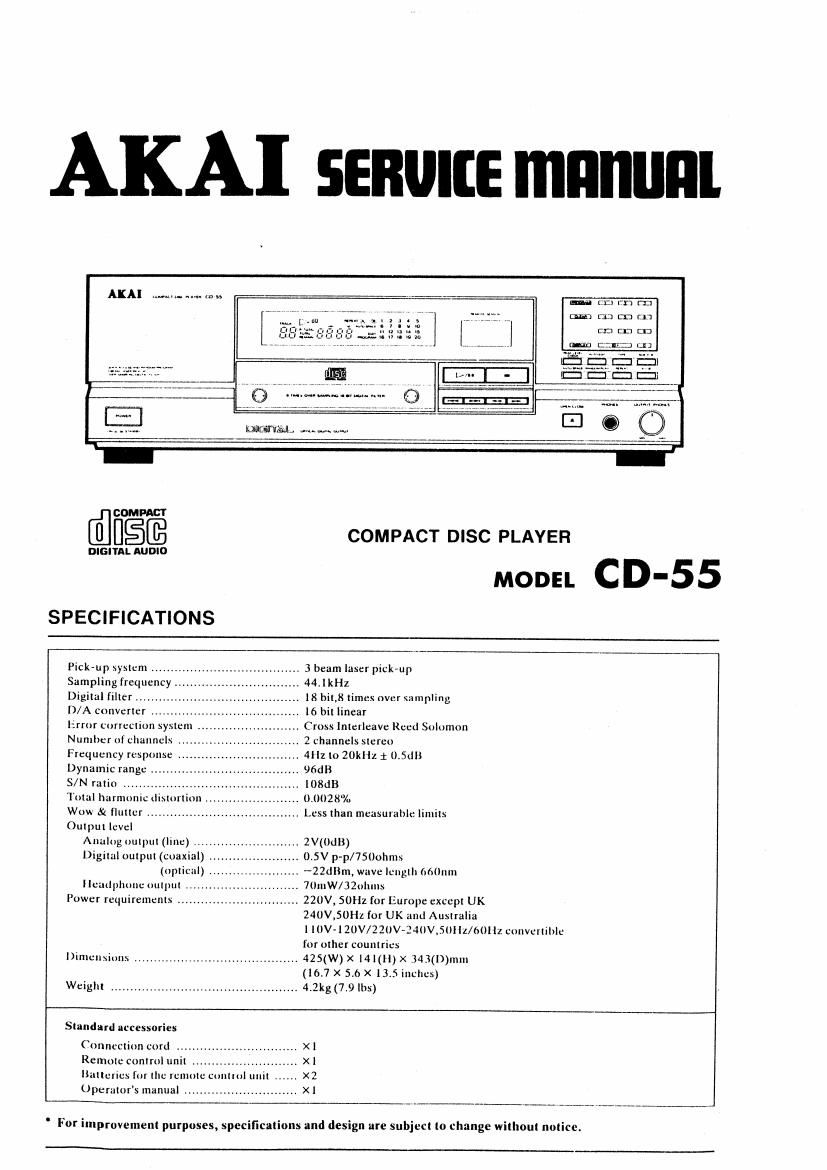
This is the 18 pages manual for Akai CD 55 Service Manual.
Read or download the pdf for free.
If you want to contribute, please mail your pdfs to info@audioservicemanuals.com.
* SAFETY- INSTRIJCTIONS
PRECAUTIONS DL'RING SERVICING
1 Paris Identiļ¬ed by [he 1 H-) symbol are critical [or
safely. Replace only will parls number speCllied.
ln addiuon re sniery. orher pans and assemblies are «per
[med rorconlormnnce Wlmsuch regulationsaslhoseap-
plying ro spurious radiaiioii,
These musl also be replaced only wirh specified replace-
menls.
Examples: RF converiers. iuner unirs. anlenna selecror
swiiches, RF cnbles. noise blocking capacnors. noise
blocking ļ¬llers. eic.
Use specified inrernal wiring. Noie especmlly:
1) Wires covered vviih PVC rubing
2) Double insulaied wires
3) High voliage leads
. Us: spemfied insulniing mnierials for hazardous live
parrs. Nore especially: -
ll lnsulanon Tape
2) PVC iubirig
3) Spacers (lnsulanng Barriers)
4) lnsulaxion sheets for transisrors
5) Plasnc screws lor lixing microswirch (especially in
lurnrable)
. When replacing AC primary side components (Hans-
loriners. power cords. noise blocking capacirors. eic.).
wrap ends of wires securely obour ilie ierniinals before
soldering.
halal?-
Observe IhaI wires do nor comeci hear producing pnrrs
(hearsmks. oxide melal film resistorsi fusible resistors.
elc ),
u
sĀ»
..
Vi
9-
* INFORMATION
7 Checlr rhnr replaced wires do noi coniaci \harp edged or
polnred puns.
3 Also check areas surrounding repaired locniions
9 L-se care lhal foreign ubyecls (screws. solder droplels.
erel d0 nol remain insldc me sel
SAFETY CHECK AFTER SERVICING
Afler servicing, inalre measuremenis of leakage-current or
resisrance in order lo derermlne lnal :(puxcd parts are acĀ»
cepmbly insulnled from lhe supply circuir
The leakage-current measurement should be done belween
accessible nieral parrs (such as chassis. ground ierrnirial.
mrcrophone Jacks. S|gnaI~|npuV0quuI connectors. arc)
and rhe earih ground ihrongh n resisier of 1500 ohrns paral-
leled mill .1 0.15 pF capaclmr. under Ihe unll-s normal
working condmons The lenknge-curreni should be less
than 0.5 mA rms AC,
The resistance measuremem should be done between JC~
cessible exposed meral p {(5 and power cord plug prongs
with the power swuch (l ncluded) -0N", Th: rcslsmnce
should be more than 2.2 Mohms.
SYMBOLS FOR PRIMARY DESTINATION
Alphabel indicates lhe desrmnuun or rhe unils as listed
beluw
Symbols Principal Desiinaiions
VOLTAGE CONVERSION (E Model only)
Beloreconnecringihepoucrcordbei :neVOLTAGESE-
LECTOR locaied on ihe renr pnnel sun a screwdriver so
than ihe correci vollagc is lndicaled.
_ USA
8 CK
C Canada
, E . Europe ieicepi us;
i _1_E9«n__.-
Auslmlll :
T . w Germany only
- U i L-niversalArea
iv . Cusiuinsersion
SE!- in; \lnL u.
PRECALTIONS I,\ REPAIRING
when repazring or Jdlusmg ihe unil. picne nnie rhe (nlr
inning pliinrs
= Do noi pui excessive pressure on ihe mecthlcuI
pnri ioperniion pan). including ihe pickrup bluzk. _is
euremely high mechiinicul precision is required in
lhese pans
When the base I) removed {or repulr or adjuslmenl.
make sure II'ILII mere are no meinl ubiecls in (he nar-
ruu in? beiween ihe PC. board or lhe mecha pans
andlhe base.
The .\I1:ro-Compuler and ihe CD signal processing
le can be damaged by siarlc elecrriciry or leakage:
fmm a soldering iron during rcpniring
Whlle ~E-Idenng. paease lake ihe precuullum againsi
leakage is in ihe llluVKmllon
, GND
4 Do noi loosen dm- \crevn In the pickup block
when handing lhe p|Ck'up black. please refer lo the
polnls lo NOTE when replacing ihe pick-up block
Keep solely {or hazardous Inuslbl: Laser Radiaiion.
DO NOT Mich ihe Luser Beam lObieciive lensi di-
recrlv.
Vlodcls [or (he some counmeļ¬. laser warning labels
are ļ¬lmed On (he null and :nsuI: of the unit. 1:
shounbelow
Read II carenilly lor your saieiy. when repairing Jr
adjusllnglne unit.
0
[DENMARK UK. LSA]
CLASS 1
LASER PRODUCT
A Label dl-l'lxed an [he UI'III
-\ LJbiI .AI'I'iXEd inside of [he urlll
mu lc: \inuL