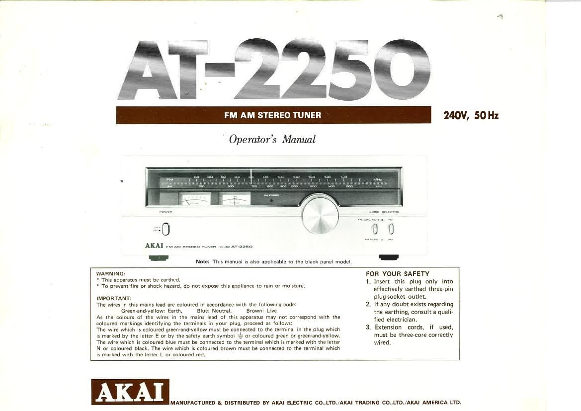
Akai AT 2250 Owners Manual

This is the 3 pages manual for Akai AT 2250 Owners Manual.
Read or download the pdf for free. If you want to contribute, please mail your pdfs to info@audioservicemanuals.com.

Page: 1 / 3
left right
Akai AT 2250 Owners Manual

Extracted text from Akai AT 2250 Owners Manual (Ocr-read)


Page 1

' Operators Manual


WW... var ammu-
0 t j i)
AKA] m. AM e'rEfiEo when "um. A'raaso W -
- Note: This manual is also applicable to the black panel model. -
WARNING: FOR YOUR SAFETY

This apparatus must be earthed.
* To prevent fire or shock hazard, do not expose this appliance to rain or moisture.

IMPORTANT:
The wires in this mains lead are coloured in accordance with the following code:
Green-and-yellow: Earth, Blue: Neutral, Brown: Live

As the colours of the wires in the mains lead of this apparatus may not correspond with the
coloured markings identifying the terminals in your plug, proceed as follows:

The wire which is coloured green-and-yellow must be connected to the terminal in the plug which
is marked by the letter E or by the safety earth symbol J?- or coloured green or green-and-yellow.
The wire which is coloured blue must be connected to the terminal which is marked with the letter
N or coloured black. The wire which is coloured brown must be connected to the terminal which
is marked with the letter L or coloured red,

1. Insert this plug only into
effectively earthed three-pin
plug-socket outlet.

2. If any doubt exists regarding
the earthing, consult a quali-
fied electrician.

3. Extension cords, if used,
must be three-core correctly
wired.

MANUFACTURED & DISTRIBUTED BY AKAI ELECTRIC CO.,LTD./AKAI TRADING CO..LTD./AKAI AMERICA LTD.

Page 2

CONTROLS

.~~.~ ....... ..--...... . AI 3.».1...

ANTENNA INFORMATIONii -
When receiving broadcast signals, the antenna being used is of
great importance. The position of the antenna is especially
important when receiving stereo broadcasts. Incorrect antenna
placement is often the cause of distortion or insufficient
channel separation.

v When an FM or AM antenna is placed high in the air,

use a lightening arrestor to protect the unit.

FM ANTENNA-i 7"; h
For FM broadcast reception, the use of a professional type
FM outdoor antenna is most ideal, but when signals are
strong, the standard accessory FM di-pole antenna will suffice.

A variety of antennas are available on the market for use

according to the specific area in which they are to be used.

Typical examples are: Indoor Antenna: For about a 20 km

(15 mile) radius from the station; 3-Element Antenna: For

about a 60 km (40 mile) radius from the station; SvElement

Antenna: For about a 80 km (50 mile) radius from the

station.

This model is equipped with both 759 and 3009 impedance

antenna terminals: 75!) Terminals: Use to connect a 750

coaxial cable from an outdoor FM antenna placed at a

distance away from the unit; 3009. Terminals: The supplied

3009 di~pole antenna is sufficient when the signals are

relatively strong.

. If in a remote area, or inside a concrete building, etc., a
multi-element outdoor antenna is recommended. In this
case, use 300 ohm terminals.

in When using TV antenna feeder wire, keep in mind that
the wire is susceptible to corrosion and lasts only a few
years. Check wire periodically as defective lead-in wire
can cause sound distortion or increased noise.

a» A TV/FM Antenna can also be used in place of an FM
antenna,

AM ANTENNA-
The AM ferrite bar antenna at the rear of the unit is
adequate for normal AM reception. Use AM antenna terminals
when signal strength is insufficient.

FM BROADCAST RECEPTION

Make connections as outlined in CONNECTIONS.

I. Turn on Power Switch.

2. Set Selector to FM position.

3. Set Mode Switch to FM AUTO/MUTE or FM MONO.
If the signal strength of the desired station is weak, FM
MONO position is recommended.

9 Knob to select desired station (FM Stereo

ight to confirm FM stereo reception).

5. Tune until the FM Tuning Meter indicator is at the center
and the Signal Strength Meter registers as strongly as pos-
sible towards the right of the scale.

6. Adjust controls of the external amplifi

AM BROADCAST RECEPTION

Make connections as outlined in CONNECTIONS.

Turn on Power Switch.

Set Selector to AM position.

Turn Tuning Knob to select desired station.

Adiust AM Bar Antenna as required. Pull out from rear
panel and position for maximum fidelity.

Tune until the Signal Strength Meter registers as strongly
as possible towards the right of the scale.

Adjust controls of the external amplifier.

As AM broadcasts are in monaural only, position of FM
Mode Switch is irrelevant.

9 I" PPN.

us

XIII! IIZIII-II
Illllf It III! 4;
Ittlulllczimlh

CONNECTIONS

Di-pole Antenna

FM Outdoor Antenna

. my... mum

AT- 2250

Connect to a deeply buried

underground bar.

" Do not connect to a gas
line, etc.

V

munm r
taint: l ulllllll

I ' l I I I I M. . 5.
.

10.

11.

12.

FM DIAL SCALE
AM DIAL SCALE

SIGNAL STRENGTH METER

When tuning in FM or AM broadcasts, tune for indica-
tion as far as possible toward the right end of the scale.
Movement of the needle to left or right indicates signal
strength.

FM CENTER TUNING METER

Turn Tuning Knob to select FM station while observing
this meter. Tune until the indicator needle comes to
the center of the meter. The Stereo Indicator Lamp
will light when FM Stereo broadcasts are being received.

FM STEREO LAMP
Lights when FM stereo broadcasts are being received.

TUNING KNOB
Rotate this knob for selection of desired broadcasts.

POWER SWITCH

FM MODE SWITCH

FM AUTO/MUTE: Will automatically receive any FM
broadcasts in stereo or monaural.

w Cuts noise between FM stations
and disturbances from weak inputs.
For listening to FM stereo broad-
casts in monaural. Left and right
channels are mixed and emitted
from both left and right speakers.
(When FM broadcast signals are
too weak for stereo separation,
MONO position facilitates better
audibility.)

FM MONO:

FM/AM SELECTOR SWITCH
Set to FM position to receive FM broadcasts, and to
AM position for receiving AM broadcasts.

AM FERRITE BAR AN I'ENNA

Pull out rom rear panel for AM reception. If signals
are not received with sufficient clarity, use an outdoor
antenna and connect to the AM antenna terminal.

FM and AM ANTENNA TERMINALS (Sea Antenna
Information).

OUTPUT JACKS (Left and Right)
Connects to inputs of external amplifier for playback.

AM Outdoor Antenna

3009 parallel FM outdoor antenna or FM

di-pole antenna.

When using a 759 coaxial cable irom
the FM outdoor antenna, connect to
the 75S! antenna terminal, and connect
the shielded ground wire to the ground
terminal.

NOTE:

If the FM broadcast station is nearby and
distortion exists, use the LOC antenna
terminals instead of the DIST terminals of
Model AT-2250 and connect in the same
way as described above.

B Speakers System