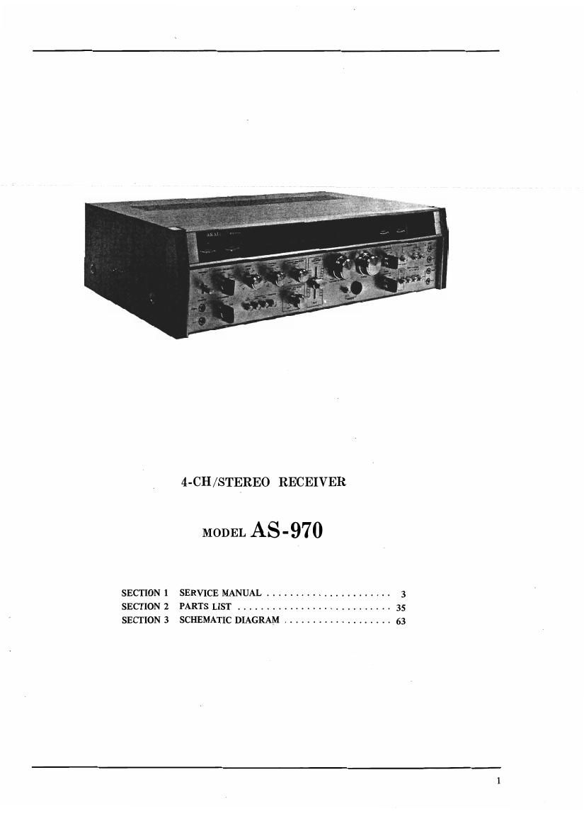
Akai AS 970 Service Manual

This is the 66 pages manual for Akai AS 970 Service Manual.
Read or download the pdf for free. If you want to contribute, please mail your pdfs to info@audioservicemanuals.com.

Page: 1 / 66
left right
Akai AS 970 Service Manual

Extracted text from Akai AS 970 Service Manual (Ocr-read)


Page 1

SECTION 1
SECTION 2
SECTION 3

4-CH/STEREO RECEIVER

MODEL AS-970

SERVICE MANUAL ...................... 3
PARTS LIST ........................... 35
SCHEMATIC DIAGRAM ................... 63

Page 2

SSZEF"

VII.

VIII.

SECTION 1

SERVICE MANUAL

TABLE OF CONTENTS

SPECIFICATIONS ................................................. 4
DISMANTLING 0F UNIT ............................................ 6
ARRANGEMENT 0F MAIN PARTS ..................................... 7
NECESSARY MEASURING INSTRUMENTS ............................... 8
CLASSIFICATION OF VARIOUS P.C. BOARDS AND INTERCHANGEABILITY ...... 9
FM TUNER SECTION ADJUSTMENTS ................................... 10
1. FM IF CIRCUIT ADJUSTMENT ..................................... 10
2. FRONT END FM IF MATCHING ADJUSTMENT .......................... 13
3. TRACKING ADJUSTMENT ......................................... 14
4. SENSITIVITY ADJUSTMENT ....................................... 14
5. SIGNAL METER SENSITIVITY ADJUSTMENT ........................... 15
6. STEREO SEPARATION ADJUSTMENT ................................ 15
7. TUNING METER CENTER ADJUSTMENT .............................. 15
8. MUTING LEVEL ADJUSTMENT

(STEREO INDICATOR SENSITIVITY ADJUSTMENT) ............ 15
AM TUNER SECTION ADJUSTMENTS .................................. 1s
1. AM IF CIRCUIT ADJUSTMENT ..................................... 18
2. TRACKING ADJUSTMENT ......................................... 19
3. SENSITIVITY ADJUSTMENT ....................................... 20
TUNING CORD THREADING ......................................... 21
POWER AMPLIFIER ADJUSTMENTS .................................... 22
1. CURRENT ADJUSTMENT AT NON-INPUT ............................. 22
2. POWER TRANSISTOR VOLTAGE DISTRIBUTION ADJUSTMENT ............. 22

COMPOSITE VIEWS OF COMPONENTS .................................. 27

Page 12

FM ANTENNA TERM [NE

75 0.
END

NOISE
ELEMENT

F ig. 8

OUTPUT INPUT
0

AM-FM RADIO
IF GENESCOPE

Fig. 7 INSTRUMENT CONNECTIONS

2. FRONT END AND FM IF MATCHING
ADJUSTMENT

1) Connect the GENESCO lead wires to the 750
FM ANTENNA TERMINALS of the Receiver as
well as to the FM IF P.C. Board output as
showri in Fig. 7.

2) Set the GENESCO to FM mode and adjust the
vertical gain of GENESCO to obtain a 10 mm
amplitude of the 0.3Vp-p calibration voltage on
GENESCO Screen and set the GENESCO attenua-
tor to 100 dB.

3) Set Receiver SELECTOR to FM AUTO, and
tuning indicator needle to extreme right end of
the dial.

4) Adjust the Upper core of Front End 1F Coil
(Fig. 18) to obtain maximum wave' height value
of 5 Curve in Fig. 8, and adjust the lower core
to obtain maximum noise level.

5) Make this adjustment again following FM Sensi-
tivity Adjustment.

l3

Page 59

FIG. 22 PHOTO OF FINAL ASSEMBLY BLOCK

FINAL ASSEMBLY BLOCK
Ref.

No. Parts No. Description Sflflm Qty Sf: Parts No. Description schfiTm Qiy
FRONT PANEL BLOCK 22-28 SK531213 Tuning Knob 91-5050 1
22-1 SP545747 Front Panel 97-5023 1 22-29 BC54S725 Cabinet 97-5035 1
22-2 SE546208 Slide Mask 93-5069 1 22-30 ZW548010 Spot Facing Washer MU-fim 4
22-3 AZ531055 Front Plate 8 91-5044 1 22-31 ZW552824 1S0 Screw, binding head
22-4x M5309 Retaining Plate Cushion 91-6043 2 4x1 8 (Black) 4
22-5 AA53114§ Fitting 2 91-5016 2 22-32x EF562691 Fuse 2.5A 250V 49-1-50 4
22-6 AA541517 Side Molding A (Right) 91.5032 1 22-33x EF424BI 1 Fuse ST-2 2.5A (CSA) 39-1-26 4
22-7 AA541528 Side Molding 13 (Left) 91-5052 1 22-34x EF575234 Fuse 6A 250V +50 1
22~8 AA531156 Side Fitting A (Right) 91-5046 1 22-35x EF563657 Fuse 3A 250v 39-1-50 1
22-9 AA531167 Side Fitting B (Left) 91-5046 1 22-35x AA539537 Fuse Holder Cover 2? 2-34-75 2
22-1ox ZS447BOS Tapping Screw #2 3x12 (BR) 6 22-37x Z5379350 1S0 Screw, pan head 3x6 2
22-1 1x 28447840 Tapping Screw #2 3x8 (BR) 2 22-38 AA545894 Remote Jack Cover 98-5062 1
22-12 AA545905 Push Button Bush 95-5061 12 122-39): EA576112 Fuse l>.c. Board A (CSA) 97-5057. 1
22-40x M569586 Fuse Angle A (CSA) 97-5056 1
ASSEMBLY BLOCK 22-41x EF277424 Fuse 51-11 mm (CSA) 39-1-28 2
22-13x AZS45736 Bottom Plate 97-5034 1 22-42x EF459843 Fuse ST-z 5A (CSA) ' 39-1-26 1
221411 28447772 Tapping Screw #2 3x6 (BR) 11 22-43x E1514822 Fuse Holder, P.Ct Board
22-1sx SA377190 Rubber Foot, LM LM-m 4 5115051 (CSA) 10-1-28 16
22-16x ZW419646 Washer (SPC) D4.Sx9.8x0.5t 4 22-44x 121539662 Wrapping Post 1x17 (CSA) 32-1-48 16
22-17x Z5463375 Tapping Screw #2 4x15 22-45x EA54944B Fuse RC. Board (CSA) 92-5022 2
(Truss) 4 22-46x M5696 10 Barrier (CSA) 97-5059 1
22-1 5 152435217 Collar For Jack MIC-5006 e 22-47x E1550912 Speaker Plug ASP-1 42-1-64 3
22-19 5K531314 Power knob 91-5064) 1 22-48x Elssz77s Short Pin Plug £0107 42-1-65 2
22-20 SK547964 Seiector Knob , 98-5080 4 22-49x AA560092 FM Antenna AFM-1 B
22-21 SK531224 Push Button Knob 91-5051 12 (5003-03) 55-1-18 1
22-22 SK531281 Single Knob 91-5057 4 22-50x AAséoom FM Antenna AFM-lA
22-23 SK545027 Slide Knob 93-51155 1 (5003-04) (J) 55-1-11 1
22.24 SK531347 Volume Knob Ring 91-5071 1 22-51)? EF562544 Fuse 6A 125V 39-1-47 1
22-25x zw493312 Washer (Nylon) D6.2x10x1t 1 22-52x EF562680 Fuse SA 125! 391-41 1
22-26 SK531358 Volume Knob 91-507: 1

22-27x 25446422 ISO Set Screw, hexagon
socket 4x8(cup/p.)

to

When ordering parts, please describe Parts Number, Serial Number, and Model Number in detail.

6O