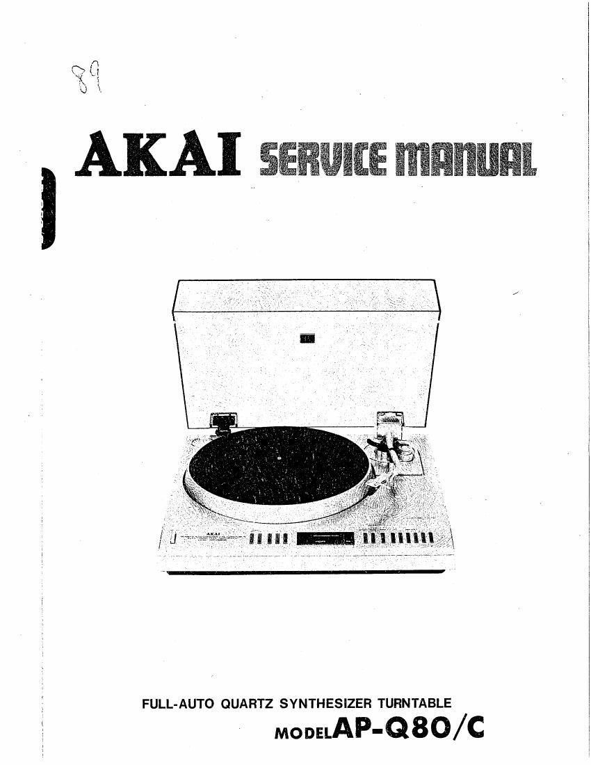
Akai AP Q80 Service Manual

This is the 60 pages manual for Akai AP Q80 Service Manual.
Read or download the pdf for free. If you want to contribute, please mail your pdfs to info@audioservicemanuals.com.

Page: 1 / 60
left right
Akai AP Q80 Service Manual

Extracted text from Akai AP Q80 Service Manual (Ocr-read)


Page 2

FULL-AUTO QUARTZ SYNTHESIZER TURNTABLE

MODELAP'QBO/ C

THIS MANUAL IS ALSO APPLICABLE TO BLACK PANEL MODEL

SECTION 1 SERVICE MANUAL ............................... 3
SECTION 2 PARTS LIST ..................................... 49
SECTION 3 SCHEMATIC DIAGRAM ............................ 61

Page 12

INTERHUPT

SA VE resislers

is the (imEr counting?

Timer counts
45 55 msec and I sec

LED digit switch on:

Which LED digit is it?

Appropriate LED
digit switch ON

Registers R E SAVE

RETURN to MAIN
(EXITi

Fig. 8 Interrupt Routine

INPUT

45msec
TIMER

55m sec
TiMER

EVALUATiON

1 igiomec v t>l0msec
TiM45=o
Asmsee 45
/ TIM 45>o
READ READ
ON OFF

TIM45 = o" 7

NO

Fig. 9 Touch Evaluation

NO, Wait

YES, touched
just before

SET TIMES

9

TIMES = "O" .7

VES

SET TIM45

SET TIMAS

Switch was touched King)
55 msec before, continuously
at least 10 msec.

Fig. 10 Flow Chart of Touch Switch Evaluation

Page 16

1) Introduction
The AP-600-A is a 4-bit type microcomputer with the
same architecture and instructions as the AP-SOO-A.
The only difference is in the number of input and
output ports These ports include 4 sets of output
ports (0T0 ~ 0T3, total 15 bits), 2 sets which may
be used as either input or output ports (100 ~ 101 ,
total 8 bits) and 3 sets of input ports (1N0 ~ 1N2,
total 12 bits).
The AP-600-A is mainly used in controlling tonearm
movement. As can be seen from the block diagram in
Fig. 14, this involves detection of the disk size of the
record on the turntable platter and position detection
of the tonearm and tonearm drive cam. And in addi-
tion to indicator LED control on the basis of com-
mand input signals from the START, CUT, ARM and
REPEAT switches, mechanism control command out-
put signals are generated.

I OPERATION SWITCH +5

5 1: 3.51m buifur

TOUCH SWITCH I:

A

®

@

Q

T or - 0
TOUCH ENABLE

I DISC SIZE SENSOR :

I

I

Q

@

®

I

I

I

I

DISC REFLECTION

+8
NW
®_ _ WAVE
SHAPE

OSC
SSOHI

I SENS. ENABLE

- CAM POSITION +5

I
I ARM POSITION SENSOR
I

': T

ISLIT PLATE

IoM i-_ j

AP»600A

To MOTOR DRIVE P.c BOARD
Moron onFF
4.

ELECTROMAGNETIC
CLUTCH

START

+3

Xroucu ENABLE

- REPEAT LEDS
MATRIX

Fig. 14 Block Diagram

Page 23

MECHANISM CONTROL
COMMAND OUTPUT

7) Mechanical Control Output Signals

Disk size detection, cam position detection and tone-
arm position detection data is processed (evaluated
and computed etc) according to the touch switch
command inputs, the resultant mechanism control
outputs appearing at the output ports (pins ® ~
(3}). These mechanism control output signals include
the turntable motor on/off signal M-Tfitm, the cam
motor on/off signal CWWF, the cam motor reverse
signal CAMREV, and the tonearm/cam magnetic
clutch on/off signal CLUTCH.

MT RON switches the MOTOR DRIVE printed circuit
board servo DC voltage on and off, while the other
signals control the cam motor and magnetic clutch
K901 via the interfaces.

K90]
Electra-magnetic
ranearm clutch

CAM MOTOR

MOTOR DBIVE R0 BOARD

+9 +5


DC
voltage to Ho ||

IC
.-____-J

Fig. 24

This completes the outline of the AP-600-A and pe-
ripheral circuits. Although this outline has not in-
cluded a description of the algorithms involved in
controlling the microcomputer, tonearm movement
together with the START, CUT, REPEAT and other
command inputs can be checked during actual play of
a record disk on the turntable.

Page 32

4-3 25 cm Record Position (Refer to Figs 36,
41 )

1) Connect a probe to VRSs center.
2) Place a 25 cm record on the platter and adjust

VR5 as in item 4-2.

5. Electro-Magnetic Clutch Constant Adjust-
ment (Refer to Figs. 37, 43)

CLUTCH RELEASE

POINT

LEAD- IN DIRECTION
DUR|N_G REPEAT

LIGHT DETECTION IOlNT-:l
LIGHT

he'd

PHOTO TRANSISTOR
(PU PLATE)

I75

INITIAL LEAD- IN DIRECTION
LIGHT DETECTION POINT

L

With repeat play, when lead-in occurs for the first
time, the PU plate with photo transistor attached
moves to the left and L2 light is input at point A.
Then the time (T) only determined by VRl is de-
layed, the clutch released at point B and the needle
descends.

Next when it leads in for repeat playback, it moves to
the right, L2 light is input at point C, T alone is de-
layed, the clutch released at point D and the needle
descends. Adjust VRl to change T and match points
B and D.

6. Angle Installation Position Adjustment
(Refer to Figs. 43, 44)

MAIN GEAR

INSTALLATION SCREW

ADJUSTMENT ANGLE %
*

Fig. 43

LED(L2)

Fig. 42

1) Place a 30 cm record on the platter and set for
lead-in at 30 cms.

2) Depress the repeat key for repeat playback.

3) Depress the start key for auto lead-in and check
the position where the needle descends.

4) Take the tone arm to the leadout position to re-
peat lead-in.
Check the position where the needle descends.

5) Adjust VRl, adjusting while repeating items 3)
and 4) until the first lead-in position and the re-
peat lead-in position are the same.

' ARM REST
TONE ARM \

Fig. 44

1) L1 detects whether or not the tone arm has re-
turned to rest, release the electromagnetic clutch
and stops the tone arm.

The adjustment angle decides the position where
the PU plate photo transistor detects Lls light by
interupting L1 s light.

2) Carry out auto return and when the tone arm has
returned to rest, loosen the adjustment angle screw
and adjust until the gap between the tone arm and
the tone arm rest is about 1mm.

Page 51

8. ASSEMBLY BLOCK (1)