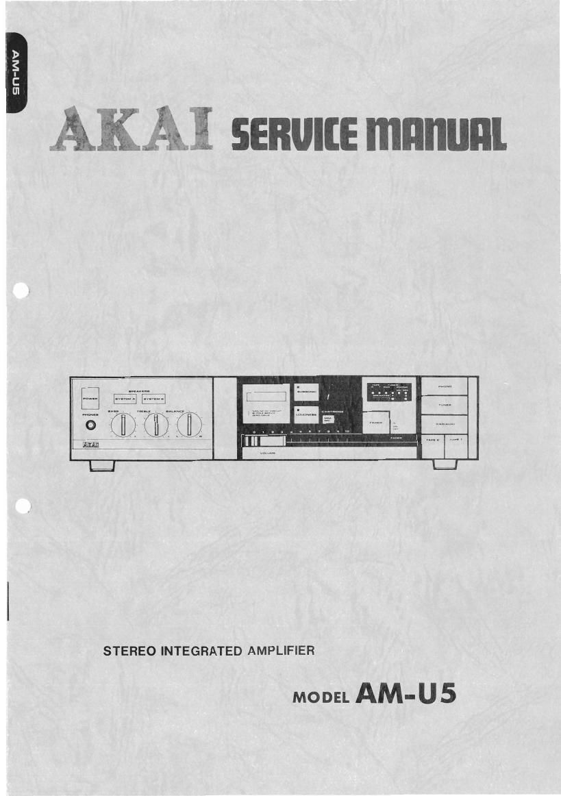
Akai AM U5 Service Manual

This is the 28 pages manual for Akai AM U5 Service Manual.
Read or download the pdf for free. If you want to contribute, please mail your pdfs to info@audioservicemanuals.com.

Page: 1 / 28
left right
Akai AM U5 Service Manual

Extracted text from Akai AM U5 Service Manual (Ocr-read)


Page 1

2mm
i

STEREO INTEGRATED AMPLIFIER

MODEL AM- U 5

Page 2

ABBREVIATIONS FOR SERVICE MANUAL

MODEL AM-U5

ABBREVIATION EXPLANATION
AC Alternating Current
RL ReLay
DC Direct Current
EQ EQualiZer
SW SWitch
MM Moving Magnet (Cartridge)
MC Moving Coil (Cartridge)
GND GrouND
INV INVerter
DET DETector

Page 10

V. CIRCUIT OPERATION

5-1 ZERO DRIVE (Refer to Fig. 5'1 & 5-2)

*1:

R24
n.
m
F

firs

TFH
Rzl
m

FR} @5

\ m
_(
x
or

a};

u

INPUY WAVEFORM OUTPUT WAVEFDRM

ARRAY;

v AMP lr AMP

DISTORTION

T9 l y

Fig. 5-2

Fig, 54

This is intended to reduce distortions in the current
amplifier stage. Voltage differences (distortion com-
ponents) between the current amplifier stage (I Amp)
input (TRS) and the main amp output (R48) when
signals have been input, are detected with TR4, and
signals will be applied to the voltage amplifier stage
loads (R15 and R16) in a manner to cancel off the
distortion components detected

5-2 OVERCURRENT DETECTING CIRCUITT (Refer to Fig. 5-3)

Figs 5-3

m rc2@nurzuoz)

SERVICE MANUAL AM»U5

Relay (RLl) is turned off for the protection oitran-
sistors against destruction and internal temperature
rises, in the event that the load is shorted or the load
impedance has dropped, causing an excessive current
to flow The voltage drop across R48 upon the
flowing of an overcurrent turns TRIO on. Then, the
TRll base will be drawn to the ground potential,
tUrning TRll on This draws the TRll collector
toward +3, and will activate the 1C2 (HA12002)
overcurrent detection, turning off relay (ILl).
In this case, the relay (RLl) will not be reset un til
after the power switch has been pushed off atleast
once.