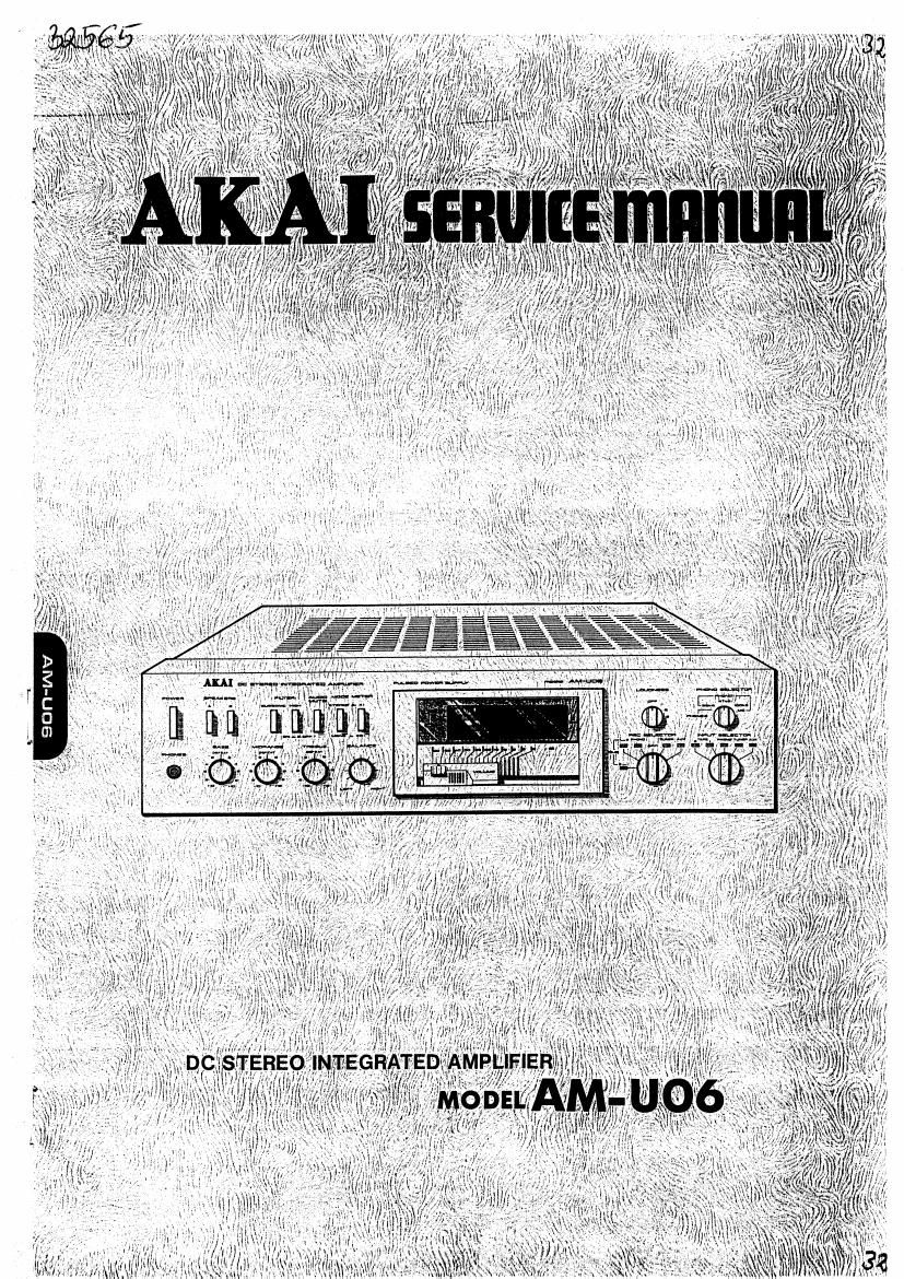
Akai AM U06 Service Manual

This is the 33 pages manual for Akai AM U06 Service Manual.
Read or download the pdf for free. If you want to contribute, please mail your pdfs to info@audioservicemanuals.com.

Page: 1 / 33
left right
Akai AM U06 Service Manual

Extracted text from Akai AM U06 Service Manual (Ocr-read)


Page 2

DC STEREO INTEGRATED AMPLIFIER

MODELAM-U06

ALSO APPLICABLE TO BLACK PANEL MODEL

SECTION 1 SERVICE MANUAL . ,
SECTION 2 PARTS LIST H
SECTION 3 SCHEMATIC DIAGRAM

,29
42

SECTION 1

SERVICE MANUAL
TABLE OF CONTENTS

TECHNICAL DATA ...................
DISMANTLING 0F UNIT. .
CONTROLS ........... L
PRINCIPAL PARTS LOCATION .
VOLTAGE CONVERSION .....
OPERATION OF PULSE POWER CIRCUIT .
. LEVEL DIAGRAM .I
. ADJUSTMENTS , I . . .

CLASSIFICATION OF VARIOUS P,C BOARDS ..... I

1. PC BOARD TITLES AND IDENTIFICATION NUMBERS I

2. COMPOSITION OF VARIOUS PIC BOARDS . .


ggéssza=F
:Romqomna

18
. 18
19

For basic :djuslments, mezsunng memoas. um cunning pnnuplas, rein (0 GENERAL TECHNICAL
MANUAL.

Page 20

HOW TO USE THIS PARTS LIST

1. This parts list is compiled by various individual blocks based on assembly process.
2. When ordering parts, please describe parts number, serial number, and model number in detail,
3. How to read List
The reference number corresponds with illustration or photo number of that particular
parts list.
This number corresponds with the Figure Number.
r-~This number corresponds with the individual parts index number
i l in that figure.
L L ,-A small it indicates the inability to show that particular part
1 2.1 15; in the Photo or illustration.
Schematic Diagram Number of individual
i-manufaciured part.
(not required (or parts order)
;-Quanlily orparticular part lequllcd.
Rel.

Nu Parts No Description 7.2"" Qty
FLYWHEEL BLOCK :1:

l2~| 15x I00425 Flywheel B|otk Assy. Col-nu. HDL :I! l

ll-l l6 244506 Flywhafl Only Rn-m I

lid 17x 24475 Eek, Flywhed Div-175 |

ll»!!! 25132 Main Mel-l C15: imam l

11-? 253060 Mai" Mual R0431 I

4. The symbol numbers shown on the P.C. Board list can be matched With the Composite Views
of Components of the Schematic Diagram or Servic: Manual.
. Please utilize separate Common List for Service Parts for Resistor Parts orders.
6. The shape of the parts and parts name, etc. can be confirmed by comparing them with the
parts shown on the Electrical Parts Table of RC. Board.
7. Both the kind of part and installation position can be determined by the Parts Number. To
determine where a parts number is listed, utilize Parts lndex at end of Parts List.

u.

it is necessary first of all to find the Parts Number. This can be accomplished by using the

Reference Number listed at right of parts number in the Parts index. (meaning of ref. no.
outlined in item 3 above).
Utilize separate Price List for Parts to determine unit price. The most simple method of
finding parts Price is to utilize the reference number.

S"

CAUTION: 1. When placing an order for parts, be sure to list the parts no. model no., and
description. There are instances in which if any of this information is omitted,
parts cannot be shipped or the wrong parts will be delivered.

2. Please be careful not to make amistake in the parts no. if the parts no. is in error,
a part different from the one ordered may be delivered.

3. Because parts number and parts unit supply in the Prcltminnry Service Manual
(Basic Parts List) may be partially changed. please use this parts list for all future
reference.

WARNING: A lNDICATES SAFETY CRITICAL COMPONENTS. FOR CONTlNUED SAFETY, REPLACE
SAFETY CRlTlCAL COMPONENTS ONLY WITH MANUFACTURER'S RECOMMENDED
PARTS.

AVERTlSSEMENT: A lL lNDlQU LES COMPOSANTS CRITIQUES DE SURETE. POUR MAINTENIR LE
DEGRE DE SECURITE DE L'APPAREIL NE REMPLACER LES COMPOSANTS DONT LE
EONCTIONNEMENT EST CRlTlQUE POUR LA SECURITE QUE PAR DES PIECES RECOM-
MANDEES PAR LE FABRICANT.

30

AC INLET SYSTEM
This model is equipped with an AC lNLET SYSTEM. Please refer to the ac lNLET SYSTEM CHART below for the
specific type. By the AC INLET SYSTEM, ac (mains) cord can be connected to and disconnected from the model
because the model is provided with socket exclusively for AC (mains) cord on its main body.
Please note, however, that certain models are not equipped with this system and has a built-in AC (mains) cord as
before.

AC INLET SYSTEM CHART

CLASS I CLASS II
E This mark i

icating double insula-

tion will be attached to machine's rear
panel

a
V
!
tilt

Picturl i
AC lNLET
to he
installed

on machines


European

commits
I"
Connect: to
machines
. AC INS! M0 0' the
EulOFlan
Connects to Dlnmlrk
h . . countries
KEEIJE meter. 2
AC (mains!
cord
Auanli: Aunt-Ii)
dill-n according diners according
(D will sock-t m wall socket
Parts List tor AC (mains) Cord Set
Standard Description Type of AC Inlet Parts No.
CEE Cord Set c132 (3 cores) 31> EW302993
Cl 1 BEAE Cord Set BEAB (3 cores) 31> 5w302994
3 SAA Cord Set SAA (3 cores) 31> EW302996
U/T Cord Set U/T (3 cores) 31> ewaozoeo
c155 Cord Set CEE (2 cores) 21> EW638144
Class [1 BEAT! Cord Set BEAB (2 cores) 21) 5w302995
saa Cord Set SAA (2 cores) 2P 13w302991
U/T Cord Set U/T (2 cores) 2? 13w302399

3]