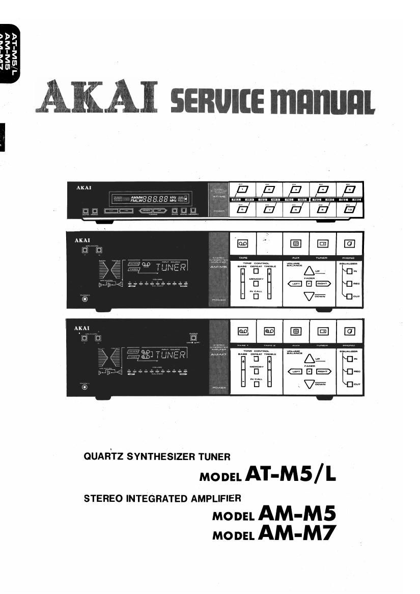
Akai AM M5 M7 Service Manual

This is the 89 pages manual for Akai AM M5 M7 Service Manual.
Read or download the pdf for free. If you want to contribute, please mail your pdfs to info@audioservicemanuals.com.

Page: 1 / 89
left right
Akai AM M5 M7 Service Manual

Extracted text from Akai AM M5 M7 Service Manual (Ocr-read)


Page 1

QUARTZ SYNTHESIZER TUNER

moon AT-M5 / L

STEREO INTEGRATED AMPLIFIER

MODEL AM-M5
MODEL AM-M7

Page 2

ABBREVIATIONS FOR SERVICE MANUAL
MODEL AT-M5/ L, MODEL AM-M5/ M7

EXPLANATION

ABBREVIATION EXPLANATION ABBREVIATION
AC Alternating Current LSI Large-Scale Integration
AF Audio Frequency LW Long Wave
AFC Automatic Frequency Control MANU MANUal
AGC Automatic Gain Control MC Memory Control
ALC Automatic Level Control MIX MIXer
AM Amplitude Modulation MM Moving Magnet (cartridge)
ANT ANTenna M. MB Memory
APPROX APPROXimately MONO MONOphonic
BCD Binary Coded Decimal MPX MultiPleX
BUF BUFfer NF Negative Feedback
CK ClocK OSC OSCillator
CMOS Complementary Metal-Oxide RL ReLay
Semi'conducmf PLL Phase Locked Loop
CPU Central Processing Unit PSC PreSC ale r
DET D ETector RAM Random Access Memory
EIAJ Electronic Industry Association RCH Right CHannel
of Japan
REG REGulator
EQ EQualizer
RF Radio Frequency
FF Flip-Flop
ROM Read Only Memory
FLD FLuorescent Display
SEG SEGment
FM Frequency Modulation
SENS SENSitivity
FREQ FREQuency
SM Signal Meter
GND GrouND
. SSG Standard Signal Generator
H High (referring to voltage)
ST STereo
IF Intermediate Frequency
STO STOre
IHF Institute of High Fidelity
SW SWitch
IND INDicator
SYNC SYNChronize
INH INHibit
THD Total Harmonic Distortion
INT INTerrupt
_ VC/O Voltage Controlled Oscillator
L Low (referring to voltage)
XT Crystal Controlled Connection
LCD Liquid Crystal Display .
Terminal
LCH Left CHannel
XTAL C TAL
LED Light Emitting Diode ys
LPF Low Pass Filter

Page 23

/\t

7-4. FM SECTION ADJUSTMENT (Refer to Figs. 7-2, 3)

' Adjustment T Adjustment Test l '
:tfp Item Point Point Rm Remarks
FM Tuning Selector to FM, Display to
1 Voltage L4 TP4 3.0V 88MHZ, Digital Volt Meter
(Low) Between TP4 & GND.
FM Tuning
2 Voltage VC4 TP4 20V Display to 108MHz
(High)
Mode to Mono. 88MHz, lkHz
3 EX??? 5 3 Output Less than 6dB (Mono, 100%) Input, 3%
s 1 y DISTORTION FACTOR
I 108MHz, lkl-lz (Mono, 100%)
4 £16335? VC1, 2, 3 Output Less than 6dB Input, 3% DISTORTION
ensi 1V1 y FACTOR
Center Tuning Meter Between
FM Center TP7 Centered TP7 & TPS, (see NOTE l)
5 V lt T2 TPS Tuning Meter Tunes only noise Without
0 age Indication interference from Broadcast-
ing
Distortion ' 98Ml-lz, 60dB, lkHz (Mono,
6 Factor T3 Output Less than 0.3% 100%) Input
pg
7 Féee Runmng VRZ TP9 l9kHziSOHz 98MHZ Non-Modulation Sig-
quuency n 31 Input
98MHz, 60dB, lkHz (Stereo,
Stereo 100%) LCH (RCH) Input,
8 Separation VR} Output More than 40dB RCH (LCH) output to Mini-
Q mum

NOTE: 1. The center tuning meter such as the ones used on model AA-RZO, 30, 40, 50>& AT-2400, 2600 can be

used for this adjustment.

If it is not available, use a digital meter (DC VOLTAGE, RANGE 20V) instead, and adjust T2 so that
it indicates 0V at the same condition.

2. For the best result, repeat step 1 through 8 for two or three times.

SERVICE MANUAL AT-MS / L

21

Page 34

2-3. OPERATION OF AMPLIFIER SECTION CONTROL IC AA-l 00 PERIPHERAL CIRCUIT
2-3-1. Display Data V
2-3-2. Digit Output of AA-100
2-3-3. Description of Input Selector
1) FUNCTION SWITCHING
2) TAPE MONITOR SWITCHING
2-3-4. Operation of Electronic Volume Control and Tone Control
1) OPERATION OF VOLUME CONTROL
2) SERIAL TRANSFER DATA
2-36. Composition of Volume IC TC9154P and Tune Control (Bass Treble) lC TC9156P
1) INTERNAL BLOCK DIAGRAM _ L
2) ATTENUATOR OF TC9154P
3) INTERNAL BLOCK DIAGRAM OF TC9156P (BASS TREBLE)
4) VARIABLE RESISTOR 0F TC9156P
S) OPERATION
6) UP/DOWN OPERATION OF VOLUME CONTROL
8) UP/DOWN OPERATION OF BASS AND TREBLE
9) BALANCE CONTROL
10) OPERATION OF FADER
23-6. The Status that will be Established When Reset Button is Pressed
2-3-7. Reset Status when Power is on
2-3-8. How to make Letters

*For the description of the above circuit which is identical to Model AA-R22/32/42, see the service manual for AA-22/
32/42.

SERVICE MAN UALAT-MS /L

31

Page 41

II. DISMANTLING OF UNIT

In case of trouble, etc. necessitating dismantling, please
dismantle in the order shown in the phogographs.
Reassemble in reverse order.

SCREWS

SCREWS

b
FRONT PANEL
SCREWS

UPPER COVER

38

SERVICE MANUAL AM-M5 /M7