Akai AM 2250 Service Manual

This is the 53 pages manual for Akai AM 2250 Service Manual.
Read or download the pdf for free. If you want to contribute, please mail your pdfs to info@audioservicemanuals.com.

Page: 1 / 53
left right
Akai AM 2250 Service Manual

Extracted text from Akai AM 2250 Service Manual (Ocr-read)


Page 1

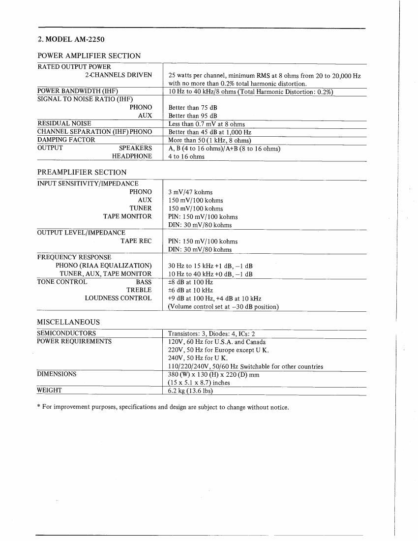
2. MODEL AM~2250

POWER AMPLIFIER SECTION

RATED OUTPUT POWER
2-CHANNELS DRIVEN 25 watts per channel, minimum RMS at 8 ohms from 20 to 20,000 HZ
with no more than 0.2% total harmonic distortion.
POWER BANDWIDTH (IHF) 10 Hz to 40 kHz/8 ohms (Total Harmonic Distortion: 0.2%)
SIGNAL TO NOISE RATIO (IHF)
PHONO Better than 75 dB
AUX Better than 95 dB

RESIDUAL NOISE Less than 0.7 mV at 8 Ohms

CHANNEL SEPARATION (II-IF) PHONO Better than 45 dB at 1,000 Hz
DAMPING FACTOR More than 50 (1 kHz, 8 ohms)

OUTPUT SPEAKERS A, B (4 to 16 ohms)/A+B (8 to 16 ohms)

HEADPHONE 4 to 16 ohms

PREAMPLIFIER SECTION

INPUT SENSITIVITY/ IMPEDANCE
PHONO 3 mV/47 kohms
AUX 150 mV/ 100 kohms
TUNER 150 mV/ 100 kohms
TAPE MONITOR PIN: 150 mV/ 100 kohms
DIN: 30 mV/80 kohms
OUTPUT LEVEL/IMPEDANCE
TAPE REC PIN: 150 mV/100 kohms
DIN: 3O mV/80 kohms
FREQUENCY RESPONSE
PHONO (RIAA EQUALIZATION) 30 Hz to 15 kHz +1 dB, 71 dB
TUNER, AUX, TAPE MONITOR 10 Hz to 40 kHz +0 dB, -1 dB
TONE CONTROL BASS :8 dB at 100 Hz
TREBLE :6 dB at 10 kHz
LOUDNESS CONTROL +9 dB at 100 Hz, +4 (13 at 10 kHz
(Volume control set at ~30 dB position)

MISCELLANEOUS
SEMICONDUCTORS Transistors: 3> Diodes: 4, ICs: 2
POWER REQUIREMENTS 120V, 60 Hz for USA. and Canada
220V, 50 Hz for Europe except U K.
240V, 50 Hz for U K.
110/220/240V, 50/60 Hz Switchable for other countries
DIMENSIONS 380 (W) x 130 (H) x 220 (D) mm
(15 x 5.1x 8.7)inches
WEIGHT 6.2 kg (13.6 lbs)

* For improvement purposes, specifications and design are subject to change without notice.

Page 2

II. DISMANTLING OF UNIT

In case of trouble, etc. necessitating dismantling, please dismantle in the order shown in the photographs.
Reassemble in reverse order.

1. MODEL AT-2250

m.__.___.m

A a SCREW 5 TUNMNG KNOB

SCREWS

SCREWS

OUVER a

SCREW

7» a;
SCREWS

FRONT PANEL

daoTToM PLATE c c scazws

Page 41

9. LIST OF INTERCHANGEABLE SEMICONDUCTORS

If, while servicing, the original parts cannot be obtained, the interchangeable parts listed below can be substituted.

Original Parts Interchangeable Parts

Description Parts No. Utilizing P.C Board Description Parts No.

ZSC930(E)(F) ET61 887 3 T3 -2501 A

28C1815(O)(Y)(GR) ET305 221 T3 -25 01A ZSC536(E)(F)(G)(H) ET246846
ZSC945L(P)(Q)(R) ETS 15 733

2SD6] 2K(D)(E)(F) ET307193 T3 -25 01A 2SC1449(K)(L) ET649034

182473 ED624903 T3 -2501A 1S1588 ED557447

RD-15E(B) ED306937 T3-2501A

DSl31A ED223547 T3-2501A

SRIOSD ED293523 T3-2501 B

ZSC1627(O)(Y) ET293253 M3-2S 01 2SD612K(D)(E)(F) ET307193

ZSC2240(GR)(BL) ET307195 M32502 2SC1222(E)(F) ET459810
2SC1312R(G)(H) ET517263

GP-20G ED245417 M3-2501 GP-ISG ED301695
HIFI SPECIAL 400V 3A ED558033