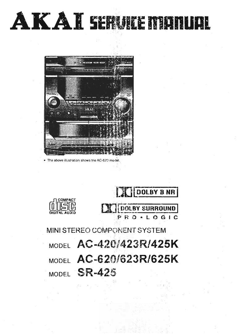
Akai AC 620 Service Manual

This is the 53 pages manual for Akai AC 620 Service Manual.
Read or download the pdf for free. If you want to contribute, please mail your pdfs to info@audioservicemanuals.com.

Page: 1 / 53
left right
Akai AC 620 Service Manual

Extracted text from Akai AC 620 Service Manual (Ocr-read)


Page 3

INFORMATION

SYMEOLS FOR PRIMARY DESTINATION
Alphabet indicates the destination ol the units as

listed below,

Symbol Princrpal Destination

USA
r [ej UK
f T Europe (except. UK)
E I Australia
IE Germany

[m universal
Custom version I

VOLTAGE CONVERSION El Model only)
Before connecting the power cord. set the VOLTAGE
SELECTOR located on the rear panel of the AC»
425K/625K so that the correct voltage (or your area

is indicated.

[u5.ue.

Y6. v7)

TEST MODE

Various kind cl test modes are installed in this units
microcomputer in order to test them on the production
line. Following test modes among the various test
modes can be used lor adlustment. operation check
or maintenance To terminate the test mode, simply
press the "POWER ONISTANDBY " button or discon-
necI the AC power cord lrum the AC outlet.

1. DECK TEST MODE

This test mode can be used lot tape speed adjustment
as well as bias oscillator trequency adjustment in TAPE
DECK section.

While pressing and holding the "TAPE II" and P" (F)
buttons. connect the AC power cord to AC outlet The
function turns to "TAPE I" and "DUEXI' as well as "
"T P l u U in El" Indicators on the FLD light when this
mode is engaged,

2. DECK CLEANING MODE

This test made an be used for cleaning of the TAPE
DECK mechanism.

Because. this mode enables engaging ot the playback.
fast forward (FF). and rewind (RWD) modes without a
cassette tape. it makes the cleaning (such as the
capstan shaft, magnetic head, pinch roller etc..) easier.
While pressing and holding the "TAPE I" and ' ' (F)
button. connect the AC power cord to the AC outlet. The
tape run Indicator lightwithout the cassette tape when
this mode Is engaged.

SPECIFICATIONS

[Tuner Sectlon]
Frequency range
FM
MW

............ B7.5-108MH2(50KHZ step)
.. 5301710KHZan)

531-1602KH2 (except U8)
.144-2BBKHZ(1KHZ step) (EUEZ/EG/BI only]
.. 3.8-!2.5MH2(5KH2 step) (Y7 only)

LW


USABLE SENSITIVITY
FM

...... 16,2dBl IHF,3%THD (except E1/E2/E3/BI)
20.2d5l IHF.3%THD (E1/E2/E3IB1)

Stereo separation ...dOdB(at 1KHz)

[AMPLIFIER Section]
Power output

(AC-420/423R/425K) 50W+50W(60hms. 10%THD. EIAJ)
40W+40W (Sohms. 1%THD. DIN)

lAC-GZOIRZGR/SZSKI 30W+30Wl60hms. 10%THD. EIAJ)
25W+25W (Gohms. 1%THD. DIN)

31 OrnV/47KQ
..,7DdE
iUHz-100KHzt-3dB)

Input sensrtlvity (AUX IN
channel separation .

Frequency response .

[DECK SECTION)
Track system .....
Frequency response

..4track. 2channel system
..... 4OHz-15KHZ (Normal tape. deB)
dOHz-ISKHZ(CIOZ tape. iidE)

.o.09% (WRMS). 015%(DIN)
DoIby a eaae (sKHz)
Dolby oft 53115 (Croz tape)

.Iess than 0.5%(normal tape at (MEI-l1)
43GB

Wow & FIutter
SIN ratio

Total harmonic distortion
Channel separation

Page 52

M55843AFP (DIGTTAL ECHO)

z '- 1-
-- 8 8 5 2 g E g
E E a a 5 3 z N E 3
.1 .l O O U 0 0 8 5 5
x 1 O 5 19 0 0
AQK
LPF'I can: 0P1 ]
REF (9
1/2 Vcc
D1 Don 1:01 |
RESET MA I N CONTROL M <-,
CLOCK
AUTO
OSCILLATOR
9 0 0 ID 9 0 3
I- u 1- N w u u O O O a o
E , .- P . . 2 U 0
x g z 3 $ E z 2 z a E > >
1- 1-
PIN No. FORT NAME IIO FUNCTION
1 Von - +5 V power supply tor dlgital section,
2 X (N l X'Ial 056 input.
3 X OUT - X'tal OSC Output.
1 4 NC - No connection.
5 TEST 1 t Test pin (fixed H in tho normal condition),
6 TEST 2 | Test pin [fixed L in tha normal condition).
7 MUTE | Mute control input (L : mute).
E - 10 NC - No wnnoction.
11 D.GND - Digital ground,
12 AGND - Analog ground,
1:1 LPFZ OUT 0 Constructs me quput side tow pass liltur tmm tn. extomaIty connected capacitot
14 LPFZ W l at resislon
15 0P2 OUT 0 Constructs the Integrator tor domodulatton from the oxtlrnatlymnnectod capacflar
16 0P2 IN I & resistor.
17 (:62 - Currant oonlral for demodulator ADM contml.
13 CCt ~ Current control for modulator ADM mntrotl
19 REF - Anatng Talaranco voItago (1/2 mm
20 OPI IN l I J Constructs the integrator for modulation ttom the externally connected capacilot
21 0P1 OUT 0 f A resistor.
22 LFFt OUT 0 Constructs the input side low passtilter tIOrn the externally connectsd capacitor l-
2: LPFt N I l resistor.
24 Vcc - l s5 v anatog power suppIy.

NJM2177A F93 (DOLBV PRO LOGlC SURROUND DECODER)

vu


L
TEE W I. w
mm
z®a J: W H
-[-d-v , mam
Moo:
HM" 1 / av~nss Ltus mm H
IMPUT mm
Hg. , A m warm 5 M
$23.35. L»: :0; 1 l L
z t 2 ° 2
E T = I '3 L
5AA5579'T (Ros DEMODULATOH)
| PIN No PORT NAME I/o l FUNCTION
l 1 OUAL o l OUALITY INDICATION OerPUT
z RDDA 0 nos DATA OUTPUT
a VFIEF - REFERENCE VOLTAGE OUTPUT
4 l MUX l MULTIPLEX SlGNAL INPUT
5 van - +5 v SUPPLY VOLTAGE FOR ANALOG PART
5 vss - GND FOFI ANALOG PART
7 CW I SUBCARRIER lNPUT To COMPARATOR
a SCOUT o sUEcARRIER OUTPUT OF RECONSTRUCTlON FILTER
9 MODE | OSCILLATOR MODE/ TEST CONTROL INPUT
10 TEST ( l TEST ENABLE INPUT
11 vss l - GND FOR DIGITAL PART
12 V00 1; +5 V SUPPLI VOLTAGE FOR DIGITAL PART
13 I 05m I OSCILLATOR INPUT _
\4 | 0500 O OSCILLATOR OUTPUT
15 l T57 O 57 kHz CLOCK SIGNAL OUTPUT
16 1 ROOI. O RDS CLOCK OUTPUT

23