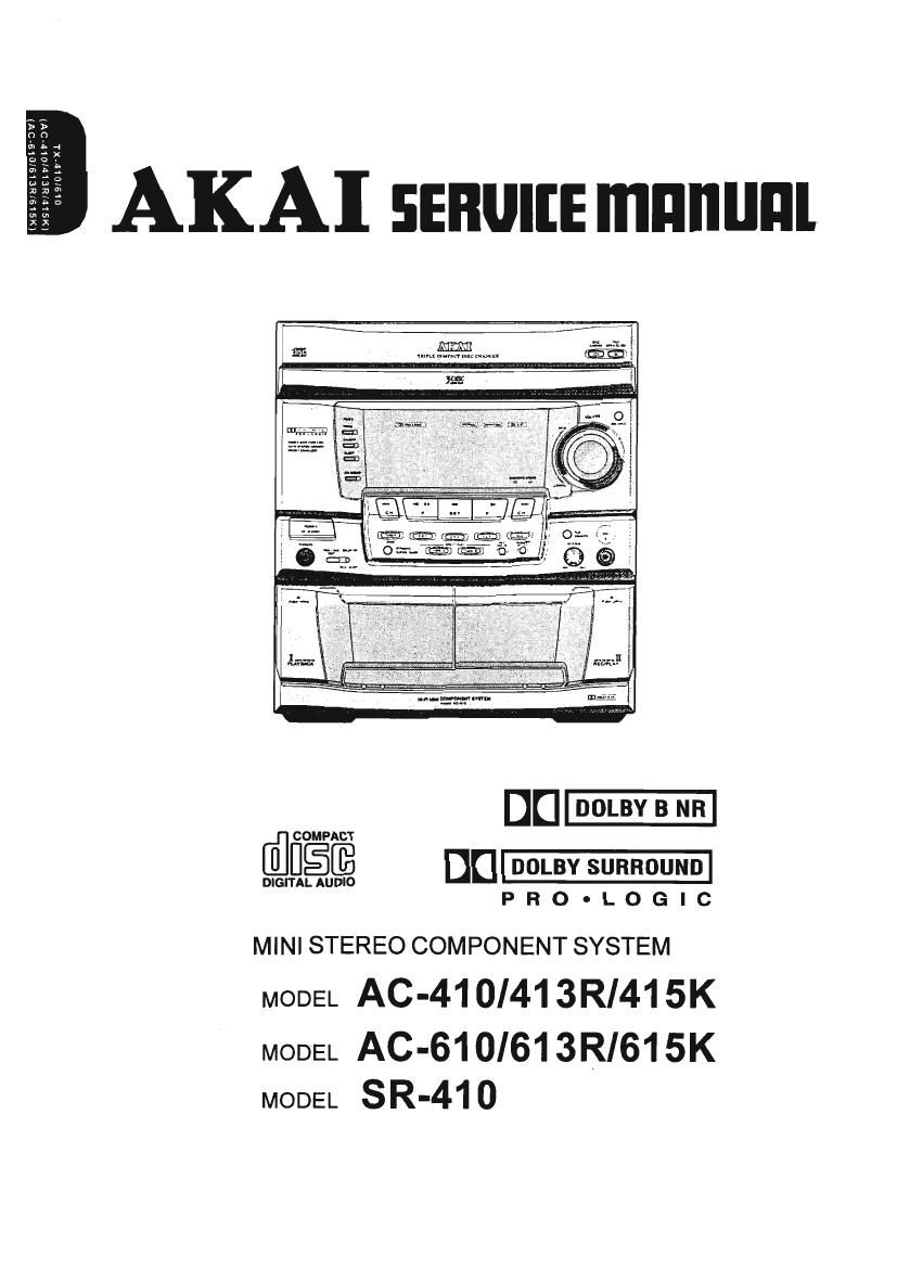
Akai AC 613 R Service Manual

This is the 75 pages manual for Akai AC 613 R Service Manual.
Read or download the pdf for free. If you want to contribute, please mail your pdfs to info@audioservicemanuals.com.

Page: 1 / 75
left right
Akai AC 613 R Service Manual

Extracted text from Akai AC 613 R Service Manual (Ocr-read)


Page 2

CONTENTS

SAFETY INSTRUCTIONS ........................................................................................... 2
INFORMATIONS ........................................................................................................... 3
SPECIFICATIONS ....................................................................................................... 4
CONTROLS ................................................................................................................. 6
I. DISASSEMBLY ........................................................................................................ 8
II. PRINCIPAL PARTS LOCATION ........................................................................... 9
III. DISASSEMBLY OF MAIN COMPONENTS .......................................................... 11
IV. MECHANICAL ADJUSTMENT .............................................................................. 16
V. ELECTRICAL ADJUSTMENT ................................................................................ 17
VI. PARTS LIST ......................................................................................................... 19
VII. ABBREVITIONS .................................................................................................... 34

Page 3

SAFETY INSTRUCTIONS

PRECAUTIONS DURING SERVICING

1. Parts identified by the Q. (*) symbol parts are critical
for safety. Replace them only with parts whose
numbers are specified.

2. In addition to safety, other parts and assemblies are
specified for conformance with such regulations as
those applying to spurious radiation.

These must also be replaced only with specified
replacements.

Examples: RF converters, tuner units, antenna selection
switches. RF cables, noise-blocking capacitors,
noise-blocking filters. etc.

3. Use specified internal Wiring. Note especially:

1) Wires covered with PVC tubing
2) Double insulated wires
3) High voltage leads

4. Use specified insulating materials for hazardous live

parts. Note especially:

1) Insulating Tape

2) PVC tubing

3) Spacers (insulating barriers)

4) Insulating sheets for transistors

5) Plastic screws for fixing micro switches

5. When replacing AC primary side components
(transformers, power cords. noise blocking capacitor.
etc), wrap ends of wires securely about the terminals
before soldering.

setting?"

6. Make sure that wires do not contact heat generating
parts (heat sinks, oxide metal film resistors, fusible
resistors, etc.)

7. Check if replaced wires do not contact sharply edged
or pointed parts.

8. Also check areas surrounding repaired parts.

9. Make sure that foreign objects (screws, solder droplets,
etc.) do not remain inside the set.

MAKE YOUR CONTRIBUTION TO PROTECT THE

ENVIRONMENT
Used batteries with the ISO symbol for
recycling as well as small accumulators
(rechargeable batteries), mini-batteries w
(cells) and starter batteries should not
be thrown into the garbage can.

Please leave them at an appropriate depot.

SAFETY CHECK AFTER SERVICING
After servicing, make measurements of leakage-current
or resistance in order to check if exposed parts are
acceptably insulated from the supply circuit.
The leakage-current measurement should be done
between accessible metal parts, (such as chassis,
ground terminal, microphone jacks, signal input/output
connectors. etc.) and the earth ground through a resister
of 1500 ohm paralleled with a 0.15 F capacitor, under
the unit's normal working condition.

The leakage-current should be less the 0.5mA rms AC.

The resistance measurement should be done between

accessible exposed metal parts and power cord plug

prongs with the power switch "ON" (if included). The

TeSIStance should be more than 2.2Mohms.

PRECAUTIONS IN REPAIRING

When repairing or adjusting the unit, please note the

following points

1.Do not put excessive pressure on the mechanical
part (operation part), including the pick-up block, as
extremely high mechanical precision is required in
these pans.

2.When the base is removed for repair or adjustment.
Make sure that there are no metal objects between
the P.C board or the mecha parts and the base.

3.The Micro-Computer and the CD signal processing
ICs may be damaged by static electricity or leakage
from a soldering iron during repairing. While soldering,
please take the precautions against leakage as in
the illustration.

GND

4.00 not loosen any screws in the pick-up block.
Please refer to NOTE when replacing the pick up
block.

5.To avoid hazardous invisible Laser Radiation, do not
look at the Laser Beam (Objective lens) directly.

6.0n model for some countries, laser warning labels
are affixed on and inside of the unit as shown below.
For your safety, read these labels carefully before
repairing or adjusting the unit.

CAUTION

The use of controls or adjustments or the performance

of procedures other than those specified herein may

result in hazardous radiation.
[ EUROPE, SCANDINAVIA, UK and AUSTRALIA ]

CIASSI LASER PRODUCT
KLASSEI LASER FRODUKT

LUOKANT LASER LAITE
KLASSI LASER APPARAT

Label affixed on the rear panel of the unit

CAUTION: INVISIBLE use: RADIATION WHEN OPEN
AND INTERLOCK DEFEATED, AVOID Bieosuas 70 BEAM
ADVARSEL: usYNLIc LAsEnsTRALINo vzo Ja-
mNo. SIKKERHEDSAFBRVDERE ER on: AF summon
UNDGAUDEITELSE FOR srnluno.

VARO: AvArrAEssA JA SDOJALUKIYUS OHITET-

TAESSA oLET ALTI'IINA NAKVMATIOMALM LASERSATE-
LVLLE

ALA KAtso sx EEsEENl

VARNING ostLIG LAsERsTRALNlNG NKR DENNA
DEL XE OFPNAD ocl-l SFARREN AR URKOPPLAD
BETRAKTA EJ STRALEN!

Label affixed on the CD MECHA BLOCK

Page 71

YSTEM CONTROL Ml-COM)

FUNCTION

'1 either sub code SO or $1 is detected.
i Sub P to W.

r 8880 read out.

pt suao 30 bit.

r 5050 read out.

l. (H : MUTE, L : CANCELL

Output to the OPERATION Ml-COM.

Reset at L.

ut irom THE OPERATION Ml-COM.

[cm the OPERATION Ml-COM. (Latching of serial data at falling
ulse.)

M38197MA-148/149FP (SYSTEM CONTROL MI-COM)

nsmission clock input from the OPERATION MI-COM. Pin No PORT NAME 0 FUNCT'ON
1 PLL CLK O PLL clock signal output to the TUNER UNIT.
0' 55P- 2 MAIN \YR; | 2 bit encoder input ior electric volume control.
imftetrocgg': S'gna' '"pm 4 PULSE 1 I TAPE 1 reel pulse input.
9 . . 5 PULSE 2 I TAPE 2 reel pulse input.
tch output to SSP. (Latchlng at fallingedge of the pulse.) 6 LEVEL 5 | ND input for surround level meter.
nsmission °I°°k output 1° SSP 7 LEVEL C | ND input for center level meter.
sition ON/OFF detection input OI Skid motor. (Input A) 8 SPANA | A/D input for spectrum analyzer indication.
SIIIOU ON/OFF detection input OI sled motor. (Input B) 9 CLK LED 0 Clock output for LED section expansion IC.
sition ON/OFF detection input of sled motor. (input 0) 10 PLL OUT 0 PLL control output to the TUNER UNIT.
n Input terminal. L when X'tal is 16.9344 MHz. H when 33.8688 MHZ. 11 STB FLD O Strobe pulse output to DOLBY PRO~LOGIC FLD drive IC.
ON/OFF control. 12 CLK FLD O Clock output to DOLBY PRO-LOGIC FLD drive IC.
ut terminal. For SENS output and servo automatic sequencer. 13 DATA FLD 0 Data output 10 DOLBY PRO-LOGIC FLD drive IC.

14 PHOTO IN I Input from the TRAY rotation position detect photo sensor.
lior spindle motor. 15 CD XLAT O Latch output for the CD MI-COM.

16 CD CLK 0 Serial clock output to the CD Ml-COM.

17 CD DATA 0 Serial data output to the CD MI

. 18 MODE SW | ND input irom the CD's open, close and clamp switches.
Dior TEST terminal. . . .
, , 19 CLK TCDK O Clock output for controlling the expanSIon IC oi the TUNER/CD/DECK sectlort.
I" 5 PLL (5'3 = "5" PLL) 20 CD SOCK o SQCK clock output to the co Ml-COM.
or master PLL' 21,85 N.C - No connection.
P output for master PLL 22 co $050 I sueo so bits serial input.

23 DATA D80 0 Serial data output for controlling the DIGITAL SOUND CONTROL IC.
voltage InPUl for 1351 __ 24 DATA 0 Serial data output to the expansion ICs (for KEY control & EVR ICs, etc.).
nput. 25 OSC PWM O Erasing OSC level control output.(PWM)
circuir constant current input. 26 BOP | Blank output pulse input. (L : blank)
compilasion voltage input. 27 EZPR DAT |/O EEP ROM serial data input/output.
rig output. (L = VSS, H = VDD) 28 EZPFI CLK 0 Serial clock output to EEP ROM.
ry circuit OFF H : Asmmetry circuit ON. 29 CD SENS | Input pin lor reading verious data from the CD MI-COM.

30 R CLK I Clock input from RDS data processor.

E for 48 bit slot. LR clockf = Fs 31 CLK DSC O Clock Output to the DIGITAL SOUND CONTROLLOFI.
DAC 32 REMOCON I Remote control signal input.
:3:po ir1gr-face_ 33 CLK AMP O imks::ii:;)m the expansmn ICs (EVR, Key control, etc. among the PRE/MAIN
nput 0 DAC' 34 CD SCOR | Sub code detect input from the CD MI-COM. (H : sub code 0 or 1 is detected)
m 00* interiace- 35 RESET l Reset input
ut to DAC. 36 X0 IN I 32.768 kHz Xtal input for clock.

37 X0 OUT 0 Output to the 32.768 kHz X'tal.

38 X IN I 8.0 MHz X'tal input.

39 X OUT 0 Output to the 8.0 MHZ X'tal.

40 GN D-D - Digital ground.

41 - 44 KEYt - 4 | Key matrix input from the operation switches.
45 - 60 DIG 1 - 18 0 System FLDs grid drive output.
61 - 80 SE61 - 20 0 System FLDs segment drive output. (SEG 17~20 : 700 series models only)

81 POW DOWN | Back up voltage detection input. (H : normal, L : Power down)

82 STEI AMP O Strobe pulse output for AMP section expansion IC.

83 OE 0 Output enable control for expansion ICs. (L: enable, H : expansion IC output -~ high

impedance).

84 STB VFI O Strobe pulse output lor EVR (electric volume) IC.

86 STB TCDK O Strobe pulse output for TUNER/DECK/CD section expansion ICs.

erminal. 87 STB PRE O Strobe pulse output for PRE AMP section expansion IC.

ien a playback disc is emphasised. L output when no emphasis. 88 STB MEC O Strobe pulse output for DECK MECHA. section expansion IC.
is control input. (H ; ON, L 3 OFF) 89 R DATA I Data input lrom RDS data processor.

to Frame Clock) output. 90 R START I Start signal input from RDS data processor.

91 V00 - +5 V power supply.

92 R RESET 0 Reset output to RDS error correction IC. (L : reset)

93 STEREO | A/D input tor the "STEREO" indicator.

out olt base) 94 TUNED | ND input for the TUNED" indicator.

J ' (TPLSI e p 95 STB LED 0 Strobe pulse output tor LED section expansion IC.
'9- l''l?a,5"l . , , 96 PLL IN I PLL control input from the tuner unit,

IZ Xtal uselllation circun Input. 97 PLL CE 0 PLL chip enable output to the tuner unit.

I2 Xtal oscillation Circuit um" 98 -VP I Negative power supply for FLD blanking.

output. (opposite phase) 99 vss - To be grounded.

OUIPUI- (in-phase) 100 VREF | Reierence voltage input. (+5 V)

Page 72

M62422FP (SOUND CONTROLLER)

Pin No PORT NAME IIO FUNCTION
1 CLOCK l Clock signal input pin for data transmission.
2 DATA I Control data input pin.
3 DVDD - Power supply for internal logic circuit.
4 VCUT - Capacitor connecting pin for vocal cut.
5 SUROUT O This pin outputs surround (LP or L+Fl) signal and vocal cut signal.
6 |N1 1 Channel 1 input pin.
7 KEYCON1 0 Output pin to the key control circuit.
8 MIC |N1 | Mic signal input pin during KARAOKE function
9 lNBASS1 | BASS resonant butterring AMP input pin.
10 NFBASS1 O BASS resonant butterring AMP output pin.
11 FBASSt - BASS BPF (resonant AMP) connecting pin.
12 INMlDt l MID resonant bufferring AMP input pin.
13 NFMIDl O MID resonant bufferring AMP output pin.
14 FMIDt - MID BPF (resonant AMP) connecting pin.
15 FTREl - TREBLE BPF connecting pin.
16 REC OUTt 0 Channel 1 REC OUT pin.
17 FBB1 l BASS boost BPF (resonant AMP) connecting pin.
18 NFBB1 O BASS boost resonant bufferring AMP output pin.
19 lNBBt | BASS boost resonant butterring AMP input pin.
20 OUT1 O Channe 1 output pin.
21 AGND - Internal analog circuit grounding pin
22 AVss - Negative power supply pin Ior internal analog circuit.
23 OUT2 O Channe 2 output pin.
24 INBBZ l BASS boost resonant bufferring AMP input pin.
25 NFBBZ O BASS boost resonant bufferring AMP output pin.
26 F882 - BASS boost BPF (resonant AMP) connecting pin.
27 FIEC OUT2 0 Channel 2 REC OUT pin.
28 FTREZ - TREBLE BPF connecting pin.
29 FMIDZ - MID BPF (resonant AMP) connecting pin.
30 NFM|D2 O MID resonant bufierring AMP output pin.
at |NM|D2 | MID resonant buflerring AMP input pin.
32 FBASS2 - BASS BPF (resonant AMP) connecting pin.
33 NFBASSZ O BASS resonant butterring AMP output pin.
34 |NBASS2 | BASS resonant buflerring AMP input pin.
35 MIC IN2 I Mic signal input pin during KARAOKE function.
36 KEYCON2 0 Output pin to the key control circuit.
37 |N2 | Channel 2 input pin.
38 SUR Fl - Time constant setting capacitor connectig pin for the surround circuit.
39 SUR C - Time constant setting capacitor connectig pin for the surround circuit.
40 AVDD - Positive power supply pin tor internal analog circuit.
41 DGND - Internal logic circuit grounding pin.
42 NC - No connection.

17