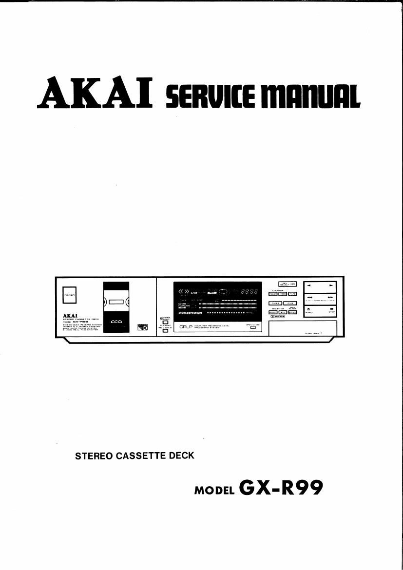
Akai GXR 99 Service Manual

This is the 113 pages manual for Akai GXR 99 Service Manual.
Read or download the pdf for free. If you want to contribute, please mail your pdfs to info@audioservicemanuals.com.

Page: 1 / 113
left right
Akai GXR 99 Service Manual

Extracted text from Akai GXR 99 Service Manual (Ocr-read)


Page 2

ABBREVIATIONS FOR SERVICE MANUAL

MODEL GX-R99

Abbreviation Explanation Abbreviation Explanation
AC Alternating Current MEMO MEMOry
A/D Analog/Digital MICOM MIcroCOMputer
AF Auto Fader MIN MINute
AM Auto Monitor MML Maximum Modulation Level
AMP AMP lifier MOL Maximum Output Level
AR Anti Recording MPX Multi PleX
AT BIAS Auto Tuning BIAS NC Not Connected (No Connection)
ATT ATTenuator NFB Negative Feed Back
BAL BALance NORM NORMal
BEF Band Elimination Filter NR Noise Reduction
BSS Blank Search System OSC OSCiJlator (OSCillation)
CH CHannel P Pulse
CN Cam Norma] P.B. Play Back
COMP COMParator QMSS Quick Memory Search System
CR Cam Reverse R Right
CRI..P Computer Recording Level Processing REC RECord (RECording)
CS Cam Stop REV REVerse
D Down ROT ROTation
D/A Digital/Analog REW REWind
DC Direct Current SEC SECond
DET DETector SELE SELEctor
DISCRI DISCRIminator SENS SENSitivity
EQ EQualizer SEPP Single Ended Push Pull
FF Fast Forward SIG SIGnal
F LD F Luorescent Display SPECT SPECT mm
FREQ FREQuency STD STanDard
FWD F orWarD SW SWitch
GND GrouND SYSCON SYStem CONtrol
H High TP Test Point
HPF High Pass Filter U Up
IND INDicator VCA Voltage Control Attenuator
IPLS Instant Program Location System VOL VOLume
L Low VOLT VOLTage
LED Light Emitting Diode VR Variable Resistor
M Motor XTAL crysTAL

Page 36

. . .and then some
. . .et autres

Quick reverse

Stereo cassette decks employ a A-Irack record»
ing/playback system, The lirst hall of the ste-
reophonic recording or playback takes place on
tracks 1 and 2 (side A), and the second halt
takes place on tracks 3 and 4 (side B). In a con-
ventional cassette deck. you must turn over the
cassette tape if you want to record or play back
on a different side The Akai GX-RQS is equipped

Inversion rapide

Les magnétocassettes stéréo incorporent un sys-
teme denregistremcut/reproduction a 4 pistes.
La premiere moitié de lenregistrement on de la
reproduction stéréophonique setTectue sur les
pistes 1 et 2 (face A), et la seconde moitié setfec-
tue sur les pisles 3 et 4 (face B). Avecun magneto-
cassette conventionnel, vnus devez retourner la
bande cassetm Si vous voulez enregistrer on re»

wrth the quick reverse system The tape travel di»
rection changes automatically at the end of the
tape. Therelore. there is no need to turn over the
cassette tape yourself.

Note:

You can also manually change the tape travel di-
rection by depressing the forward or reverse
button without first pressing stop. The direction
indifators will show the tape travel direction (<(
0T )) .

Attention!

For quick reverse operation. always use a tape With very clear

leader tape sections.

0 When a prerecorded tape is used for one-cycle (forward to
reverse) recording, the tirst one second of the reverse side of the

tape will not be erased
Please manually erase this section.

0 During quick reverse operation. no recording will be made for 0.6

second.

0 The IEII SEIEII'IIII has no effect during intro scan and blank search

operation 5

The microprocessor brain" and infrared "eye" of the Akai GX-RQQ allow for

maximum convenience in your recording and playback operations

Playback

1. Press the Reverse selector (IIEI SELECT) to set the mode,

: Indicates the tape can travel in only one direction depend-

ing on which button is depressed either (4 i or (>)

B Indicates one full cycle. The tape will play to the end oi side
t,reverse, play side 2 and then stop

C: Indicates infinite play back. The tape wrll continue to
reverse and playback both sides until you change the lunc-
Ion,

Record

>

0L0

produire sur I'autre face. Le GX-R99 Altai est
équipé dun systéme dinversion rapide. Le sens
de detiiement de la bande change automatique-
merit a la {in de la bande. Vous navez done pas
besoin de retourner vous-méme la bnnde cassette.
Remquue:

Vous pouvez égalemcnt changer Ie sens de déflle-
ment de la bande est appuyant sur la touche da-
Vance ou de retour sans avoir a appuyer sur la
touche darrét. Les indicateurs de sens indiquent
le sens dc détilement de la bade («cu»).

Attentlm! i i;

0 Pour une utilisation do Iinversion rapids, uttiisez toujours one btimiayant

des section we claires de hande amoroc. «- .
uune bande pré-enregistree est mitisée pour un enregistrémmt uri
cycle davmoe en return), la premierescwndedc Iautre Em as In band:
as sera pas effaoée. . v . .

Effacez manuenemem cette section. .

O Pendant ta function dinversiun rapine, aucun enrégisttemerrt rte setlec-

were pmdant 0,8 sewn-1c. i .

_ gr.
u Le selectem dinversion (IE9 SELEIT) ua pas dielfel pendant lesilfonctions

de balayage dtntroduction et de recherche des bhncssonores. _
Le oerveau du microprocesseur et les yeux infrarouges du GX-R99 vous

A

Reproduction
l. Appuyez sur le sélecteur dinversion (IE! filial) pour régler
1: mode.

A : Indique que la bande ne peut défiier que dons tin sens, scion
) Ia touche qui est enfonoée: soil (4 ), soil (> ).
B :Indique un cycle complet. La bande sera reproduitejusqua

Ia fin de la face 1. sinversera, Ia face 2 sets rewoduite. et la
bande sarréterat

) C :Indique une reproduction a lintmi. La bandecontinuera it
sinverser et a étre reproduite jusqué oe que ious changiez

Ia fonction,

1. Press the HEB/MUSE ( 0 1 button to standby for recording

2. Press the Rev, Selector to set the mode

A : Same as above only in recording mode

8: In this mode. the Akar GXVRQQ wrll record one complete

Enregistlement
-) 14 Appuyez sur la touche denregistrement/paure ( I ) pour
_. passer nu mode dattente denregistrement.

cycle (side A and side B) then go into continuous playback
of the just recorded tape

Appuyez sur Ie sélecteur dtnversion (IEV SElEll) pour regler
Ie mode.

2.
- , t A 4 s
D A : Identrque a cr-dessus, mars sur le mode d enregsrrement.
B :

Sur ce mode, 1e GX-R99 Altai enregistrera un cycle oomplet

Auto Tape Tuning

The Auto Tape Tuning function which takes place automatical-
Iy whenever the Rec, button is depressed, produces the maxir
rnurn performance from any type of tape. The GX»R99 sets ope
timurn Elias, Equalization and Sensitivity for Normal. Chrome or
Metal position tapes-all within a few seconds. This assures
low distortion. high output,tlat frequency response. more accuV
rate meter readings and better Dolby NR tracking.

8qu erasing
Previously recorded rriusrc is erased as new recordings are made

However. to erase an entire tape, depress the amplitiers input selector (AUX
or TAPE 2) whose input jacks are not connected and then depress the

REE/MUS 0 land play (b ) buttons to start recording plank tape,

16

(face A at face B). puis se mettra en reproduoion continue
de in bande qui vient juste d'étre enregjstree.

Syntomsatron automathue de bande

La function de synwnisation automatique dc bante qui setfec-
tue automariquement Iorsque Ia touche denregistremcnt est en-
clenchée, donne Ies performances maximum aiec mimporte
quel type do bands. Le GX-R99 regle Ia polarisation, Iégalisatior et la sensibi-
lité optimales pour les bandes a position non-hale. chrome ou mm -tout oela
en quelques secondes. Ceci assure une {aible distorsion, une sorte elevée, une
réponse en fréquence linéaire. des indications plus préciscs del'indicaleur et
un meilleur alignement Dolby NR.

Effacement total

La musique précedemment enregistrée est etTacee lorsque de nruveaux enres
gistrements sont ctTectués.

Cependant, pour enacer In bande entiere iI taut appuyer sur la electeur den-
tree de lomplificateur (AUX ou TAPE 23 dont les jacks d'entrée no sont pas
connectés, puis appuyer simultanément sur les touches denegistrement/
panse ( I ) et de lecture (V) pour commencer lenregistrement.

oIIrenI Ia facilite absolue des operations denregstrement clde reproduction.

Page 37

The Auto Monitor
System

What is an auto monitor
system '?

The independent recording and playback heads in
combinatdion with two independent ampgfilers (one
or recor ing and another for playbac ets you
listen to a recording as It is being made This is
called tape monitoring. By switching the tape monia
tor system during recording. you can compare the
just recorded music (TAPE position) to the source
music (SOURCE position), in this way you can make
sure that you have set the recording input levels cor-
rectly, The tape monitoring system of the GX-R99 is

rrr: mow

called auto monitor system". Beside letting you manually set the tape moni-
tor system, it also does it automatically. When the GXVRSS is recording. the
auto monitor system is set automaticallyto TAPE and during recording stands
by. it is set automatically to SOURCE.

There is no need for you to set the auto monitor system yoursell.

Recordlng Enregisttemcnt
Sou rce Result
Source Raullal

Encoder W Encoded tape
Encoder" Band: encode:

) -) A Boostedsolt a -
sounds

WWW Sensuouxamplme

Tapenolse

Bruitdehande


Loud saunas
Sous forts
sort sounds
Sum dull!

Systéme automatique
do contrtiIe

Quest-ce quun systéme
automatique de controls?

Admomwon

a Les tétss indépendantes rtemegistrement at de reproduction
combinées i deux amplificaleurs independants (l'un pourlm-
registrement. t'autre pour in reproduction), yous pennant-rt
découter un enregistrsment pendant quil seflmoe. Coolest
appelé controle de bands. En commutnnt le system: de mn-
tréle do band: pendant lenregistrcmenl, vouspouvez compo,
rer la musiquc qui Vienl juste d'élre enrogstrée (position
hands-TAPE) A la musique do source (position SOURCE).
Cette me'lhode vous permet de vous murer quc vous nvez
correctemsnt réglé les nivenux d'entrée denrdgistremenl. Le
systems do control: (to bands du GX-R99 est appele' systems
automotiqueds controls". Non sculement il vous permsi dc ro'gler manuoliement 1e Sysr-
téme dc contrélz tie bands, mais ll I: fail également automatiquement. Lotsque 1e GX-R99
Akfli enmgislre, 1: systems auwmalique cl: oontréle est aulomatiquement réglé sur TAPE,
et pendant lntlu'tte denregistrement. il est Iutomltiquement réglé stir SOURCE.
Vous navez donD Pas min derésler yous-mime le system automatique decontrfile.

Playback Reproduction

7306 Result

Band: Résultat
Encodcdtape W Denoder
Hand: encodes Loud sounds WWW Low: iounu.

-@ a «x- W:
Boosted sort sounds W soitscunqs W

Sons doux amphfiés Sons doux raw-s ,

Tape nurse Lowered

tape no se
E i do b d
"" " Bruitdcbandedimlnue

1 .What is Dolby n0ise reduction (NR) system ?
When you record without Dolby NR system. you can't hear the solt sounds
very clearly because they are masked by noise added by the tape during
recording The Dolby NR system reduces this annoying tape noise.

The Dolby NR encoder circuit boosts the low-level signals (soft sounds)
during recording and at playback.the Dolby NR decoder lowers the low-level
signals by exactly the same amount to restore the low-level Signals to their
original levels At the same timetape noise is lowered bythe same amount,
The result is reduction only in the unwanted tape noise,

2. What is the difference between Dolby B-type
and C-type NR system?
e C

B-type: This ist onventional Dolby NR system. It boosts or lowers the
low-level signals at high lrequencies only (more than 5 kHz) and reduces
tape noise by todB.

C-type: Compared to the Dolby B, it operates at lower frequencies (from
_500 Hz) for uniform noise reduction across the audible spectrum. Tape noise
is reduced by as much as 20dB.

Therelore. you get better results with Dolby C. however when you are playing
back tapes recorded with the conventional Dolby NR system. set the selector
to Dolby B, Dont lorget to always set the ltltllv Ill system before recording or
playing back a tape.

3. What is double process Dolby NR system?

In the conventional Dolby NR system, one circuit acts bot as an encoder
and as a decoder and is swrtched to become either one according to the
need. In the double process Dolby NR system, there is an encoder circuit in
the recording amplilier section and a decoder in the playback amplifier sec
tion. The double process Dolby NR system is used in cassette decks with 3
independent heads (recording, playback and erase), Therefore when record»
mg with Dolby NR. you can immediately confirm the eflect ol the Dolby NR
system by monitoring thejust recorded music.

' Dolby" and the doubleD symbol are trademarks of Dolby Laboratories
Licensing Corporation (Manulactured under license lrom Dolby Licens-
ing Corporation.)

Systeme Dollty till

1. Quest-ce que le systéme ole rétluction de bruit
(llll) Dolby?

Lotsque vous emegistrez sans systems Dolby NR. Von; ne pouvez pas enlanltre Iris Claire-
ment 1%: sons doux Dame quils soul masqués per lo bruit ajouté par la band: pmdantl'enrcv
gimmenl. Le systéme Dolby NR reduit oe bruit dc bande ennuyeux.

Le circull encodeur Dolby NR amplifie les signaux die laible nivcau (sons ibux) pendant
l'enregsu'ement, cl, a la reproduction, lc déoodeur Dolby NR redul't les iiguux de faible
nivenu d'exaclement la méme quantilé pour nmener court-oi i leurs niveauiloriginnux. Lo
bruit tie bands est en méme temps diminué do In mime qmntité. Scul le brur. tie bands in-
de'sirahle est don): réduit,

2. Quelle est la difference entre les systémes Dolliy
lilttypeBett eC?

Type-B: C fil le systéme o yNR conventionnel, I] namplifie ou l're reduitles Signnux de
£313; niveau qnaux hautes iréquennes (supériemes a 5 kHI), el redui! Ie brill tie band: do

-c Compare nu Dolby a, il an alliance Stir dos fréquenoes plus nurses opanlr de 500
Hz pour une réduction uniform: du bruit sur tout to spec: audible. Le hrul ae halide est
réduitdejusqun 20 on.

Vous omens: done a: meillcurs résultats ave: Dolby c; «mam, lorsque rous mpmdur-
sez ties halides enregistrées avec le sysléme Dolby NR conventinnncl, réglrz 1e iélwteur
sur Dolby a, Noubliez pas die toujtmrs tester le system nut Ill avant d'encgislrer ou de
teproduire une bands.

3. Quest-ce que le systéme Dolby NR double

procéde ?
Dans Ie systéms Dolby NR conventimnel. un settl circuit agit ii la this on tantqu enoodzur
er décodeur. at il est commute pour devenir lun dz cos deux elements seloii [as bsooins.
Dans le systeme Dolby NR double procédé, i] y a un circuit enuodeur dens 1! Sutton amplifi-
cateur denrcgistrement et un circuit déoodsur dans In section amplificatemde reproduc,
lion. Le sysleme Dolby NR double procédé at utilise dans les mamétocaoettcs ayant 3
tétos indépendantes (emegistrcment, rsproduci et armament). Lars d'm amsgistre-
merit am Dolby NR, ll you: extdmtcpos 'ble do ven r imméd'mement I'Gflild usystéme
Dolby NR en levrpduisant la musique qu. vientjuste d elre enregistrée.
Dolby et le symbol: Double D sont dos marques déposées do Dolby Loturalon'es Li-
censing Corporation. (Fabriqné sous licence do Dolby Laboratoris Licensing
Corporation).

Page 56

PRE AMP ADJUSTMENT CHART (for more detail, see 7-2-1 to 7-2-3)

Adjustment Test Tape & Adjustment
Step Item Mode Supply Signal Point Result
Connect INPUT VR4 (L) TPI (L)
1 DC 33'3 STOP PIN of P30 with GND VR4 (R) TPI (R) o t 100 mV DC
333 Hz 0 VU Tape VRS (L)
FWD PLAY (315 Hz 0 VU Tape) VRS (R) LINE OUT
2 RB Level -6.l 10.1dBm
333 Hz 0 VU Tape (-5.5 1 0.1 dBm)
REV PLAY (315 Hz 0 W Tape) Confirmation
LINE OUT
VR6 (L)
3 PB EQ FWD PLAY 10 kHz RE E0 Tape VR6 (R) 7205 2 02 dBm
REV PLAY 10 kHz P.B EQ Tape Confirmation -20.5 t 20 dBm
4 METER TAPE MONITOR 1 kHz LINE IN VR3 (L) +1 V'U indication on VU
Sensitivity SOURCE (-5.2 dBm LINE OUT) VR3 (R) METER Display
LINE OUT
315 Hz 0 vu Tape VR2 (L) -5.5 t 0.3 dBm
5 Dolby Decoder FWD PLAY VR2 (R) When Dolby ON
(333 Hz 0 VU Tape) (-6.1 2 0.3 dBm)
LINE OUT
6 MPX Filter REC 19 kHz LlNE IN FL2 (L) MIN
FLZ (R) When MPX sw ON
. REC/PLAY No Signal Input LINE OUT
7 3:313? t METAL Tape PM (L) MIN
REC/PAUSE (REC VR MAX) FLl (R)
. LINE OUT
8 MAGS, 3" REC/PLAY No Signal Input VL1 (L) MIN
' METAL Tape VL1 (R)

7-2-1 PB EQ AMP ADJUSTMENT
(TUNING P.C board is disconnectable from
METERP.C board)

1) DC Balance
a. Remove connector of P30 (PB HEAD Connector)
13. Connect INPUT SIGNAL PIN of P30 Pin @, Q4)
to GND.
0. Adjust VR4 so that the voltage of TPl will be
0 i 100 mV DC.
2) PB Level
3. FWD Play Back 333 Hz (AT-750773) or 315 HZ
(AT-750773) PB level adjustment tape and adjust
VRS so that the LINE OUT level will be 333 HZ
to -6.1 t 0.1dBm or 315 Hz to -5.5 i 0.1 dBm.
b. REV Play Back 333 Hz or 315 Hz PB level adjust-
ment tape and confirm so that the LINE OUT
level will be -6.] i 0.6 dBm (333 Hz) or -5.5
x 0.6 dBm (315 Hz).
3) PB E0
3. FWD Play Back 10 kHz PB EQ adjustment tape
(AT-750778) and adjust VR6 so that the LINE
OUT level will be -20.5 i 0.2 dBm.
b. REV Play Back 10 kHz PB EQ adjustment tape
and confirm so that the LINE OUT level will
be -20.5 i 2.0 dBm.

7-2-2 METER SENSITIVITY ADJUSTMENT
a. With the monitor SW to SOURCE and the meter

SERVICE MANUAL GX-R99

SW to VU, Supply lkHz to LINE IN, a IkHz
signal -5.2 dBm at LINE OUT.
b. Adjust VR3 so that the +1 VU.

7-2-3 DOLBY ADJUSTMENT

1) Dolby Decoder Adjustment

a. FWD Playback 315 Hz PB level adjustment tape
(AT-750773).

b. Adjust VR2 so that the LINE OUT level will be
-5.5 i 03 dBm when Dolby ON. (At 333 Hz PB
level adjustment tape, LINE OUT level will be
-6.1 i 0.3 dBm)

2) MPX Filter adjustment

2. Set a blank tape and set to REC/PLAY mode.

b. MPX filter SW OFF, input a signal of 19 kHz from
LINE IN.

c. Adjust FLZ so that the LINE OUT level will be at
minimum when MPX filter SW is turned ON.

3) BIAS Filter Adjustment

a. Set a metal tape and set to REC/PLAY (0r REC/
PLAY -> REC/PAUSE).

b. Adjust PM so that the LINE OUT level will be at
minimum when the recording volume is set to
MAX and the monitor SW to SOURCE.

c. Set a metal tape and set to REC/PLAY mode.

(1. Adjust VL1 so that the LINE OUT level will be at
minimum when the monitor SW is set to TAPE.

35