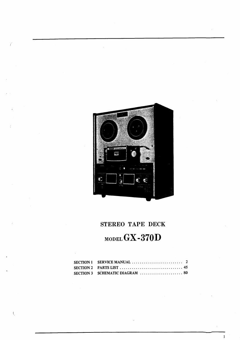
Akai GX 370 D Service Manual

This is the 84 pages manual for Akai GX 370 D Service Manual.
Read or download the pdf for free. If you want to contribute, please mail your pdfs to info@audioservicemanuals.com.

Page: 1 / 84
left right
Akai GX 370 D Service Manual

Extracted text from Akai GX 370 D Service Manual (Ocr-read)


Page 1

STEREO TAPE DECK

MODEL GX - 3701)

SECTION 1 SERVICE MANUAL ......................... 2
SECTION 2 PARTS LIST ............................... 45
SECTION 3 SCHEMATIC DIAGRAM ..................... 80

Page 2

:-

SECTION 1

SERVICE MANUAL

TABLE OF CONTENTS

SPECIFICATIONS ................. . ............... 3
MEASURING METHOD ............................. 4
DISMANTLING OF UNIT ........................... 6
MECHANISM ADJUSTMENTS ....................... 8
HEAD ADJUSTMENTS ............................. 11
AMPLIFIER ADJUSTMENTS ........................ l 3

. TRANSPORT MECHANISM ....................... l6
. SERVO MOTOR OPERATING PRINCIPLES ............. 31

DIFFERENTIATION 0F SYSTEM CONTROL
SCHEMATIC DIAGRAM & PC. BOARD ......... 33
COMPOSITE VIEWS OF COMPONENTS ........ . 34

Page 4

II. MEASURING METHOD

1. TAPE SPEED DEVIATION

Frequency
(903701) counter
Line output input
Fig. 1

As shown in Fig. 1, connect a Frequency Counter to

the Line Output of Model GX-370D. Playback a '

1,000 Hz pre-recorded test tape. Take a Frequency
Counter reading at the beginning, middle, and end of
tape winding during playback. The maximum value
of these respective readings will represent tape speed
deviation.

2. WOW AND FLUTTER

Wow and Flutter
Meter input

g GX-370D
Line output

Fig. 2

Method A

As shown in Fig. 2, connect the Line Output of
Model GX-370D to the Input of a Wow and Flutter
Meter. Playback a 3,000 Hz pre-recorded test tape
and take a Wow and Flutter Meter reading at the
beginning, middle, and end of tape winding. The
maximum value of these respective readings will
represent the Wow and Flutter.

Method B

Supply a 3,000 Hz sine wave signal from an Audio
Frequency Oscillator and make a recording on a
blank tape at the beginning, middle, and end of tape
winding. Rewind and playback the resultant signal.
Measure Wow and Flutter with 3 Wow and Flutter
Meter. (The Wow and Flutter value of Method B will
be close to twice that of Method A.)

3. FREQUENCY RESPONSE

. GX-370D
Audio 01m Line
Frequency put :1 A.T.T. input Line
Oscillator output
High Sensitivity
V.T.V.M.
Fig. 3

For measuring Frequency Response, connect instru-
ments as shown in Fig. 3 and proceedas follows:

1) Supply a 1,000 Hz sine wave signal to the Line
Input of Model GX-370D from an Audio Frequen-
cy Oscillator through an Attenuator.

2) Set recorder to recording mode and turn recording
level control volume and line output level control
volume to maximum. Adjust attenuator to obtain
a +4 dB V.T.V.M. reading.

3) Under conditions described in 2) above, readjust
attenuator so that the Line Output is -16 dB, and
record 30 to 24,000 Hz spot frequencies.

4) Rewind tape and playback from the beginning.
Take V.T.V.M. spot frequency readings and plot
values on a graph.

NOTE: When measuring Frequency Response, new
tape should be used.

4. SIGNAL TO NOISE RATIO

GX-3 70D
Line output

High Sensitivity
V.T.V.M.

Fig. 4

As shown in Fig. 4, connect a High Sensitivity
V.T.V.M. to the Line output of Model GX-370D.
Playback a 250 Hz 0 VU pre-recorded test tape and
measure the output. Then remove the tape and
measure the noise level under the same condition.
Convert each of the measured values into desibels.

Page 11

HEAD ADJUSTMENTS

:0

ERASE 8
HEAD (FWD!

F]

1. HEAD HEIGHT ADJUSTMENT

(See Figs. 14& 15)

l) Playback Head

21) For FWD playback mode head height adjust-
ment, during FWD playback, turn head height
control screw (d) to left and right until the
upper edge of the tape as it passes the head is
aligned with the upper edge of channel 1 head
corev

b) For REV playback mode head height adjust-
ment, during REV playback, turn head height
control screw (e) to left and right until the
lower edge of the tape as it passes the head is
aligned with the lower edge of channel 1 head
core.

\bw-HEAD CHASSIS

Fig. 14
:0

ERASE & REC.
HEAD (REV)

Tribe

Fig. 15

2) Recording and Erase Heads

a) For FWD recording and erase hed height
adjustment, at FWD playback mole, adjust
head height control screws (0 (g) 31d (h) by
turning to left and right until the upper edge
of the tape as it passes the head is algned with
the upper edge of channel 1 recording head
core.

b) For REV recording and erase held height
adjustment, at REV playback mete , adjust
head height control screws (j) (k) aid (1) by
turning to left and right until the lover edge of
the tape is aligned with the lower edge of
channel 1 recording head core.

3) When making the various head height aduStments,

confirm that the tape and head core sumce is at a
right angle with the head chassis during t:p e travels

ll

Page 80

SECTION 3

SCHEMATIC DIAGRAM

GX-370D SCHEMATIC DIAGRAM

>80