Akai DPS 12 Service Manual
This is the 41 pages manual for Akai DPS 12 Service Manual.
Read or download the pdf for free.
If you want to contribute, please mail your pdfs to info@audioservicemanuals.com.

Extracted text from Akai DPS 12 Service Manual (Ocr-read)
Page 1
.m -.t
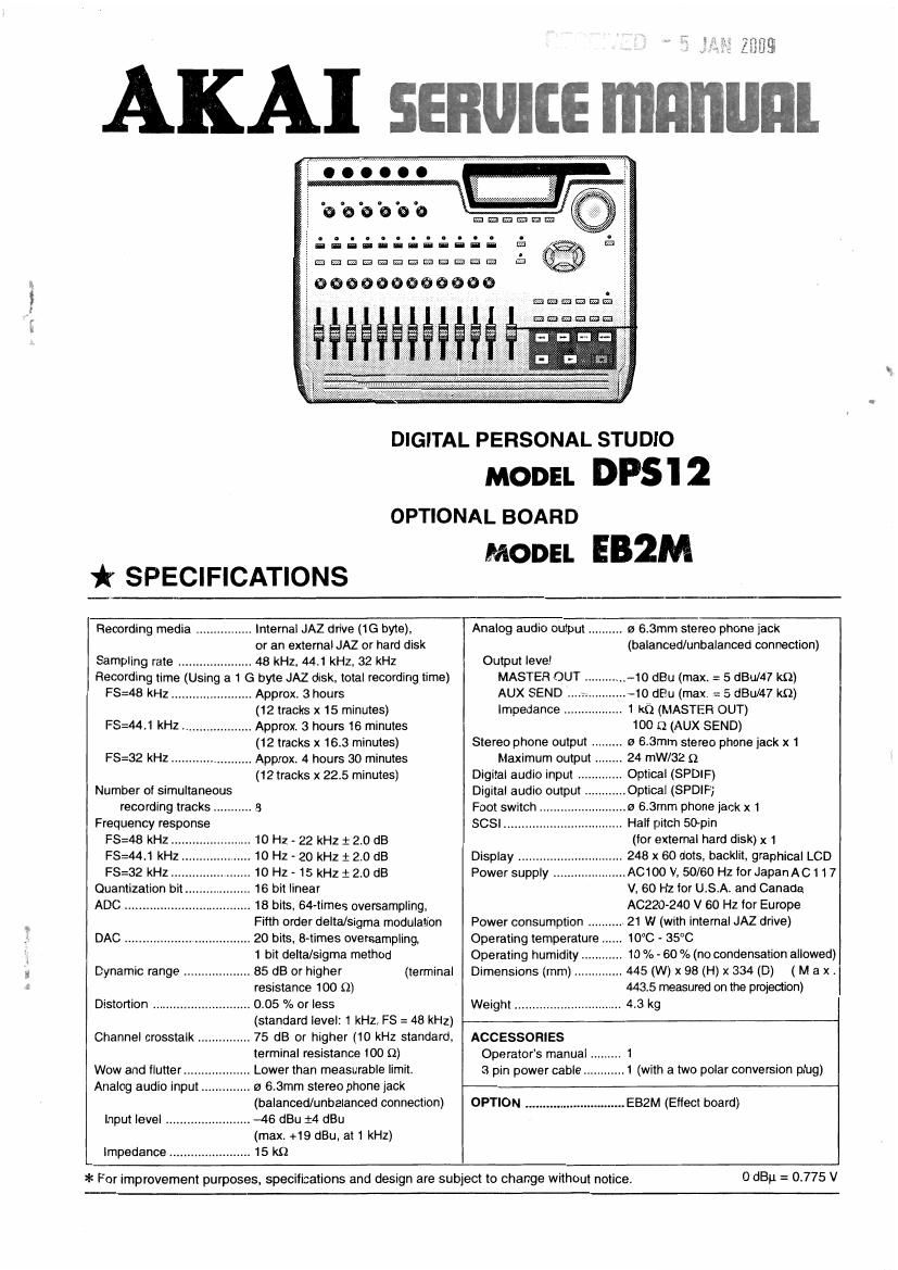
DIGITAL PERSONAL STUDIO
MODEL DPS'I 2
OPTIONAL BOARD
* SPECIFICATIONS
MODEL EB2M
Recording media Internal JAZ drive (1G byte),
or an external JAZ or hard disk
Sampling rate ..................... 48 kHz, 441 kHz, 32 kHz
Recording time (Using a 1 G byte JAZ disk, total recording time)
FS=48 kHz .. Approx. 3 hours
(12 tracks x 15 minutes)
FS=44.1 kHz .................... Approx. 3 hours 16 minutes
(12 tracks x 16.3 minutes)
Approx. 4 hours 30 minutes
(12 tracks x 22.5 minutes)
FS=32 kHz
Number of simultaneous
recording tracks ........... 8
Frequenqr response
FS=4B kHz ., 10 Hz < 22 kHz i 2.0 dB
FS=44.1 kHz
FS=32 kHz
Quantization bi
ADC ...............
10 Hz - 20 kHz 1 2.0 dB
10 HZ- 15 kHz 12.0118
16 bit linear
18 bits, 64-times oversampling,
Fifth order delta/sigma modulation
DAC .................................... 20 bits, 8-times oversampling.
1 bit delta/sigma method
Dynamic range ................... 85 dB or higher (terminal
resistance 100 Q)
0.05 % or less
(standard level: 1 kHz, FS = 48 kHz)
Channel crosstalk ............... 75 dB or higher (10 kHz standard,
terminal resistance 100 a)
Lower than measurable limit.
a 6.3mm stereo phone jack
(balanced/unbalanced connection)
Distortion
Wow and llutter ......
Analog audio input
Input level ........................ -46 dBu i4 dBu
(max. +19 dBu, at 1 kHz)
Impedance 15 kfl
Analog audio output .......... to 6.3mm stereo phone jack
(balanced/unbalanced connection)
Output level
MASTER OUT 10 dBu (max. = 5 dBu/47 kQ)
AUX SEND 10 dBu (max. .= S dBu/47 k0)
Impedance 1 kfl (MASTER OUT)
100 a) (AUX SEND)
o 6,3mm stereo phone jack x 1
24 mW/32 (2
Optical (SPDIF)
.Optical (SPDIF)
6.3mm phone jack x 1
Stereo phone output ,
Maximum output .
Digital audio input
Digital audio output
Foot switch
SCSI Half pitch 50~pin
(for external hard disk) x 1
Display 248 x 60 dots. backlit. graphical LCD
, 0100 V, 50/60 HztorJapanAC117
V, 60 Hz for USA. and Canada
AC220-240 V 60 Hz for Europe
21 W (with internal JAZ drive)
Power supply .,
Power consumption
Operating temperature 10C - 35°C
Operating humidity ..... 10 % - 60 % (no condensation allowed)
Dimensions (mm) .............. 445 (W) x 98 (H) x 334 (D) (M a x.
443.5 measured on the protection)
43 kg
Weight
ACCESSORIES
Operators manual ..
3 pin powercable
1
.1 (with a two polar conversion plug)
OPTION ............................. EBZM (Effect board)
* For improvement purposes. specifications and design are subject to change without notice.
0 dBu = 0.775 v
Page 2
* SAFETY INSTRUCTIONS
* INFORMATIONS
PRECAUTIONS DURING SERVICING
1. Parts identified by the A symbol are critical for safety.
Replace them only with the pans number specified.
2. In addition to safety, other parts and assemblies are
specified for conformance with such regulations as those
applying to spurious radiation.
These must also be replaced only with the specified
replacements.
Examples : RF converters, tuner units, antenna selector
switches, RF cables, noise blocking capacitors,
noise blocking filters, etc.
3. Use specified internal wiring. Note especially :
1) Wires covered with PVC tubing
2) Double insulated wires
3) High voltage leads
4. Use specified insulating materials for hazardous live parts.
Note especially :
1) Insulation Tape
2) PVC tubing
3) Spacers (insulating barriers)
4) insulation sheets for transistors
5) Plastic screws for fixing micro switches
5. When replacing AC primary side components (trans-
formers, power cords, noise blocking capacitors, etc),
wrap the ends of the wires securely around the terminals
before soldering.
sir-s»?
6. Make sure that wires do not contact heat prodUCing parts
(heat sinks. oxide metal film resistors. fusible
resistors, etc.).
7. Check that replaced wires do not contact sharp edged or
pointed parts.
8. Also check areas surrounding repaired locations.
9. Make sure that foreign objects (screws, solder droplets,
etc.) do not remain inside the set.
SAFETY CHECK AFTER SERVICING
After servicing, make measurements of leakage-current or
resistance in order to determine that exposed parts are
acceptably insulated from the supply circuit. The leakage-
current measurement should be done between accessible
metal parts (such as chassis, ground terminal, microphone
jacks, signal input/output connectors, etc.) and the earth ground
through a resistor of 1500 ohms paralleled with a 0.15 pF
capacitor, under the units normal working conditions.
The leakage-current should be less than 0.5 mA rms AC. The
resistance measurement should be done between accessible
exposed metal pans and power cord plug prongs with the
power switch (it included) ON". The resistance should be
more than 2.2 M ohms.
SYMBOLS FOR PRIMARY DESTINATION
Unit destinations are indicated with letters as shown below.
Symbols Principal Destinations
U.S.A
UK
Canada
Europe (except UK)
Japan
Australia
Germany
Universal Area
SERVICE MANUAL
Custom version