Akai CDX 105 Service Manual
This is the 20 pages manual for Akai CDX 105 Service Manual.
Read or download the pdf for free.
If you want to contribute, please mail your pdfs to info@audioservicemanuals.com.

Extracted text from Akai CDX 105 Service Manual (Ocr-read)
Page 1
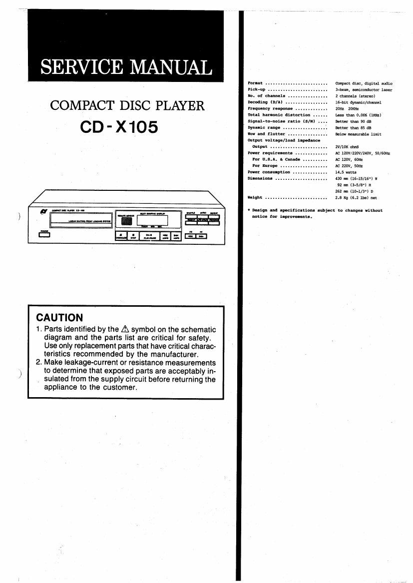
SERVICE MANUAL
COMPACT DISC PLAYER
CD - x105
a mum on.
mum-amoun-
CAUTION
1. Parts identified by the A symbol on the schematic
diagram and the parts list are critical for safety.
Use only replacement parts that have critical charac-
teristics recommended by the manufacturer.
2. Make leakage-current or resistance measurements
to determine that exposed parts are acceptably in-
. sulated from the supply circuit before returning the
appliance to the customer.
Porn-t
Pick-up . . .
not of channel:
Decoding tn/A)
pnquenoy renponne .
Total harmonic distortion .
Signal-co-noiac ncio (S/l)
Dyna-it: tango . . . .
Havana flutter .. ..
Output vanish/load impedance
Output ...........
Pane: requituzenta .
Pat u.s.n. a cannde .
Po: mrope .......
me: cmunption
Dilenuions .........
Height .......
We disc. digital audio
3M, semennducmr laser
2 channels (stereo)
16-bit dynamic/manna;
20Hz 20m:
Less than 0.061: (liq-1:)
Better than 90 on
Better than 85 as
Below measurable limit
zv/mx ems
M: 12W/220v/mv, SO/GOH:
AC 120V, 5082
AC 220v, 5on
14.5 watts
430 m (16-15/16) u
92 m (3-5/8") n
252 m (lo-US") n
2.5 Kg (6.2 ms) net:
' Daliqn and lpeciiicltim subject to changes without
notice tor uptown-nu.
Page 2
Caution Concerning Handling of The Laser
The following label has been affixed to the unit, listing the proper
procedure for working with the laser beam.
(UL and xx-v model only)
rumor Cmes WITH ems
nuns 21cm. summers» J.
PART 1040i 10
cuss l
LASER PRODUCT
(CSA model only)
Gianna) own To mum
mum oops.
02mm: EN vEmu nu was
CANADlEN as LEEGTHIWE
SEULENENT
Cautions When Removing The Laser Pick-up For
Repairing '
Before removing the laser pick-up, short-circuit the
terminals by soldering. This is to prevent damage to
the pick-up during removal operation.
Solder the pick-up terminals.
Detach 2 lead connectors.
Cautions When Replacing The laser Pick-up
Insert the 2 [Disk-up lead connectors into the
connector PCB.
Detach the short-circ'uited pick-'up terminal soldering.
* The terminal is factory sldered ofr protection, so
use the same procedure when replacing the pick-up when
a new one.
Pick-up Head Ass y
( Pattern Side )
Connector
Board
©
(9
0
0
O
0
O
O
0
0
00000000
00000000
00000000
Solder this Position