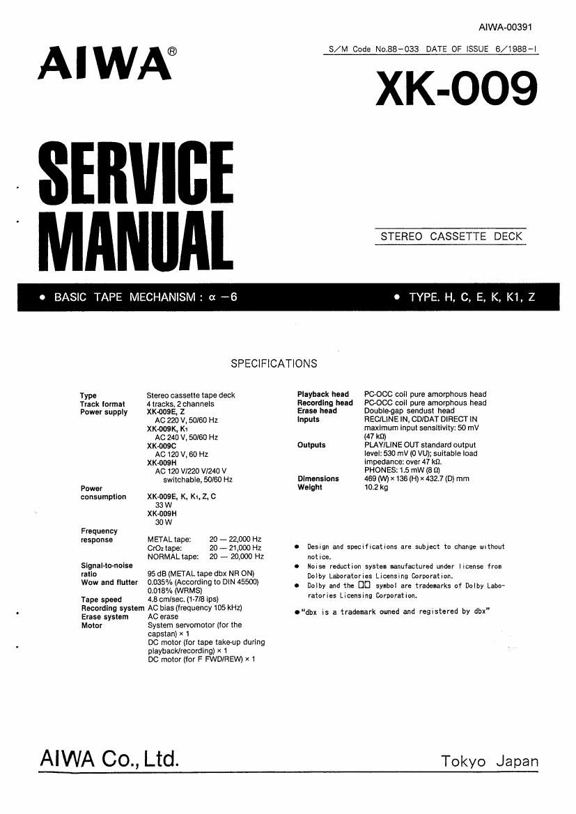
Aiwa XK 009 Service Manual

This is the 27 pages manual for Aiwa XK 009 Service Manual.
Read or download the pdf for free. If you want to contribute, please mail your pdfs to info@audioservicemanuals.com.

Page: 1 / 27
left right
Aiwa XK 009 Service Manual

Extracted text from Aiwa XK 009 Service Manual (Ocr-read)


Page 1

AlWA-OO391

l I W n ® S/M Code No.88-033 DATE OF lSSUE 5/1988-I

XK-009
: SERlllBE

0 BASIC TAPE MECHANISM: -6 0 TYPE. H, C, E, K, K1, 2

SPECIFICATIONS
Type Stereo cassette tape deck Playback heed POOCC coil pure amorphous head
Track lormat 4 tracks, 2 channels Recording head PGOCC coil pure amorphous head
Power supply XK-ODSE, Z Erase head Doublegap sendusl head
AC 220 V, 50l60 Hz Inputs REC/LINE IN, CDIDAT DIRECT IN
XK-009K, K1 maximum input sensitivity: 50 mV
AC 240 V, 50/60 Hz (47 k9)
XK-OOBC Outputs PLAYILlNE OUT standard output
AC 120 V, 60 Hz level: 530 mV (0 VU); suitable load
XK-009H impedance: over 47 kt).
AG 120 V1220 VI24O V PHONES: 1.5 (W (8 (I)
switchable, 50/60 Hz Dimensions 469 (W) x 136 (H) x 432.7 (D) mm
Power Weight 10.2 kg
consumption XK-OOSE, K, KI,Z, C
33 W
XK-OUSH
30 W
Frequency
response METAL tape: 20 - 22,000 Hz
Cr02tape: 20-21300 Hz I Design and specifications are subject to change without
NORMALlape: 20 ~ 20,000 HZ notice.
Signal-[Ovnoise 95 dB(METALt db NR ON) 0 Noise reduction system manufactured under license from
m '0 ape X Dolby Laboratories Licensing Corporation
WOW and uer ggggy/Z mgarsdrg i0 DINASSOO) O Dolby and the DU symbol are trademarks cf Dolby Labo-
Tape speed 4:60m/sec.(1~718ips) retories Licensing Corporatiom
Effgtysgjésmm fig Sigiéfrequencyws kHz) 0"de is a trademark owned and registered by dbx
Motor System servomotor (for the

capstan) x 1

DC motor (for tape take-up during
playback/recording) x 1

DC motor (for F FWD/HEW) x 1

AiWA 00., Ltd. Tokyo Japan

Page 2

DlSASSEMBLY INSTRUCTIONS

1. Mechanism ASSY Removal
1) Remove side wooden panels R/L and the steel cabinet.

2) Remove 2 screws and take out the stabilizer solenoid.
(See Figure-1)

Fig-l

3) Remove the cassette lid in the direction of arrow @.
Remove 6 screws and lay out the wires, then remove
the front cabinet in the direction of arrow @.

(See Figure-2)

O4VEEIEM3- 7nyl~=l=vl52w l~
Pull out the wires. Front cabinet

Cassette lid
Fig-2

4) Remove 5 screws and push button (EJECT), then pull
out the mechanism ASSY in the direction of the arrow.
Take care of the hook of the lever plunger ASSY at
this time. (See Figure-3)

17") DUEII?LCZ)6
EZElI??.

Remove the spring and
then the screw.

new 11-4 '-
EJECT Jo;

Push-button. EJECT HQ?!

2. Cassette Holder Removal
1) Remove 2 screws in the EJECT state and then remove

the holder in the direction of the arrow. Be
carefull that the lever (EJECT) is also removed at
this time. (See Figure-4)

2) Turn on SW10?) and 50107 to operate the mechanism in
this state.

l//\-t EJECT
Levert EJECT

Fly-4

3. Main-2 C.B Removal
1) Remove 4 screws and lift the min-2 circuit board.
(See Figure-5)

7B) HR? EX) h
Front cabinet

Fig-5

I bli-TEJy'r-ASSY
_/Lever plunger Assy
~ II E zjuym w:-

PE-sprinm Lever