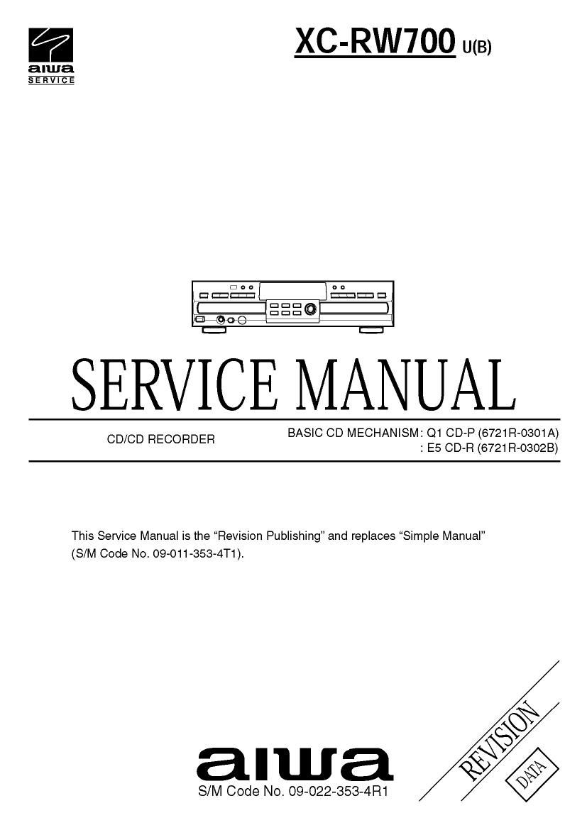
Aiwa XC RW700 Service Manual

This is the 90 pages manual for Aiwa XC RW700 Service Manual.
Read or download the pdf for free. If you want to contribute, please mail your pdfs to info@audioservicemanuals.com.

Page: 1 / 90
left right
Aiwa XC RW700 Service Manual

Extracted text from Aiwa XC RW700 Service Manual (Ocr-read)


Page 1

a XC-RW7OO U(B)

alwa
SERVICE

SERVICE MANUAL

BASIC CD MECHANISM: Q1 CD-P (6721R-0301A)
: E5 CD-R (6721 R-osozB)

CD/CD RECORDER

This Service Manual is the Revision Publishing and replaces Simple Manual
(S/M Code No. 09-011-353-4T1).

§

alwa £9

S/M Code NO. 09-022-353-4R1

Page 2

TABLE OF CONTENTS

PROTECTION OF EYES FROM LASER BEAM DURING SERVICTNG -1/1 ........................................... 3
SPECIFICATIONS ...................................................................................................................................... 4
ACCESSORIES LIST -1/1 ......................................................................................................................... 5
DISASSEMBLY INSTRUCTIONS ......................................................................................................... 6 ~ 7
ELECTRICAL MAIN PARTS LIST ....................................................................................................... 8 ~ 10

TRANSISTOR ILLUSTRATION .
BLOCK DIAGRAM .
WIRE HARNESS DIAGRAM -1/1
SCHEMATIC DIAGRAM

1/1OCD-P 1/2 SECTION ......................................................................................................................... 17
2/10 CD-P 2/2 SECTION ........................................................................................................................ 18
3/10 CD-R 1/4 SECTION ......................................................................................................................... 21
4/1OCD-R 2/4 SECTION ......................................................................................................................... 22
5/10 CD-R 3/4 SECTION ......................................................................................................................... 23
6/10 CD-R 4/4 SECTION ......................................................................................................................... 24
7/10 I/O SECTION ................................................................................................................................... 27
8/10 POWER SECTION ........................................................................................................................... 30
9/10 FRONT SECTION ............................................................................................................................ 32
10/10 POWERSW, PHONE SECTION .................................................................................................... 34
WIRING

1/11CD-PC.B-SIDEA-..
2/11CD-P C.B -S|DE B .
3/11 CD-R C.B-SIDEA
4/11CD-RC.B-SIDEA-.

5/11 I/O C.B -S|DE A- ............................................................................................................................... 28
6/11 I/O C.B -S|DE B- .............................................................................................................................. 29
7/11 POWER C.B ..................................................................................................................................... 31
8/11 FRONT C.B ...................................................................................................................................... 33
9/11 POWER SW C.B, PHONE C.B ........................................................................................................ 35
10/11 CD-P SECTION .............................................................................................................................. 36
11/11 CD-R SECTION .............................................................................................................................. 37
VOLTAGE CHART ............................................................................................................................ 38 ~ 41
WAVEFORMS ................................................................................................................................... 42 ~ 46
IC BLOCK DIAGRAM ........................................................................................................................ 47 ~ 53
IC DESCRIPTION ............................................................................................................................. 54 ~ 55
FL DISPLAY-1/1 ..................................

MECHANICAL EXPLODED VIEW -1/1
MECHANICAL MAIN PARTS LIST-1/1

COLOR NAME TABLE .........................

CD-P MECHANISM EXPLODEDVIEW-1/1 ............................................................................................ 60
CD-P MECHANISM MAIN PARTS LIST -1/1 ............................................................................................ 61
CD-R MECHANISM EXPLODED VIEW -1/1 ........................................................................................... 62
CD-R MECHANISM MAIN PARTS LIST -1/1 ............................................................................................ 63
TROUBLE SHOOTING ..................................................................................................................... 64 ~ 89

Page 5

ACCESSORIES LIST -1/1

REF NO PART NO Kégm DESCRPTON

1 S8-29R-DTO-02C MANUAL ASSY OWNERS AADR640
2 S7-11R-2N0-13H REMOTE CONTROLLER ASS AADR610

Page 6

DISASSEMBLY INSTRUCTIONS - 1/2

1 . Case Top Removal 4) Release CN803 from CD-P CB and release CN803. CN804
1) Release 6 screws. from POWER C.B, AND release CN805. CN806 from l/O
2) Lift the Case Top with holding the back of it and remove it. C.B. (See Fig. 3)

5) Release Knob VOL and REC and release 7 tabs (A- G). and
2. Panel Front Removal (See Fig .1 , 2) then release Panel Front in the direction of the arrow.
1) Tuni over the set. Insert a screwdriver into slow A and B (shown (See Fig. 3)

in Fig. l), and move the manual pull-out lever of Tray Disc in

the direction of the arrow. to pull out the Tray Disc. POWER 0-3

(See Fig. l)

Fig. 8
Tray Disc
Fig. 1
2) Turn over the set to the original status. and remove the Door 3. Front (R) CB, Front (L) CB Removal
CDP and Door CDR in the direction of arrows. (See Fig. 2) 1) Release 9 screws. (See Fig. 4)

3) Push in the Tray Disc in the direction of the arrow. (See Fig. 2)

\ Door CDR
Door CDP

4. Power SW CB Removal
1) Release 2 screws (B). (See Fig. 4)