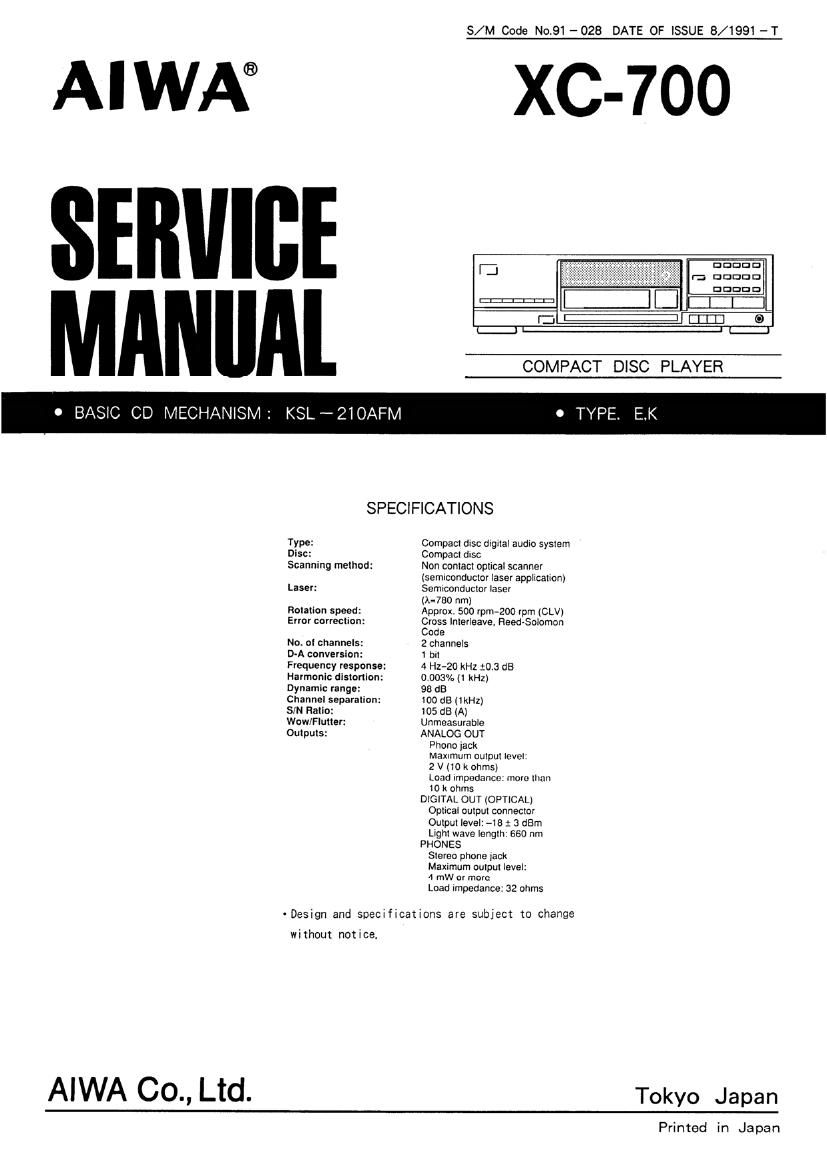
Aiwa XC 700 Service Manual

This is the 27 pages manual for Aiwa XC 700 Service Manual.
Read or download the pdf for free. If you want to contribute, please mail your pdfs to info@audioservicemanuals.com.

Page: 1 / 27
left right
Aiwa XC 700 Service Manual

Extracted text from Aiwa XC 700 Service Manual (Ocr-read)


Page 1

S/M Code Not91-028 DATE OF ISSUE 8/1991 -T

AIWA® XC-7OO

E .. V . . - DDDDD
, v rt. DDDDD

DDDDD

MAN"Al COMPACT DISC PLAYER

0 BASIC CD MECHANISM: KSL-ZIOAFM 0 TYPE E.K

SPECIFICATIONS
Type: Compact dxsc drgnal audio system
Disc: Compact dlSC
Scanning method: Non contact optlcal scanner
(semiconductor laser appltcahcn)
Laser: Semiconductor laser
(A1080 nm)
Rotation speed: Approx. 500 rpm-200 rpm (CLV)
Error correction: Crass Interleave, Reed~SoIomon
Code
No oI channels: 2 channels
D-A conversion: 1 but
Frequency response: 4 Hz-20 kHz $0.3 dB
Harmonic distortion: 0.003%(1 kHz)
Dynamtc range: 98 (18
Channel separatton: 100 dB (1 kHz)
SIN Flatio: 105 (SE (A)
Wow/Flutter: Unmeasurable
Outputs: ANALOG OUT
Phone lack

Maxrmum output Ievet
2 v (to x ohms)
Load Impedance, mom than
to k ohms
DIGITAL OUT (OPTICAL)
ODIICBI output connector
Output Iavet' >18 1 3 dBm
nghI wave length: 660 nm
PHONES
Stereo phone Jack
Maxrmum output level:
4 mW or more
Load Impedance: 32 ohms

- Design and soemficatxons are subject to change

without notice.

AIWA CO., Ltd. Tokyo Japan

Printed in Japan

Page 2

DISASSEMBLY INSTRUCTIONS

1. Tray" Removal (See Figure-1)
1) Remove the Cabinet. Steel".
2) AFor AUTOMATIC operation
Press the OPEN/CLOSE button to eject
the Tray".
.For MANUAL operation
Insert a flat-head screwdriver into the hole at
the bottom of the arrow to eject the Tray.
(See Figure - l)
3) Loosen 2 screws (®) and pull out the Tray"
toward you.(See Figure-2)

Tray

0/ 5%

2.

"CD Mechanism" Removal (See Figure-2)

l) Loosen 2 screws (®) and remove
the Tray" .remove 3 screws (6)) and
CD Mechanism'.

remove

CD Mechanism
[ . Tnv
Fia - 2
Fig - 1

I ACCESSORIES/ PACKAGE LIST
PART NO. REF. COMMON
CHANGED T0 N0. PART NO. DESCRIPTION MODEL QTY

I *80-A03-901-018 INSTRUCTION BOOKLET 35$ 1

2 *80-A63-951-019 REMOTE CONTROLLER RC-C104 YB X 1

3 *37-034-773-010 CORD. PIN R-237W-1M 1

Page 3

PROTECTION OF EYES FROM LASER BEAM DURING SERVICING

This set employs laser. Therefore. he sure to Iollow carelully
the instructions below when servicing.

WARNING"

WHEN SERVICING. DO NOT APPROACH THE LASER EXIT
WITH THE EYE TOO CLOSELY. IN CASE IT IS NECESSARY
TO CONFIRM LASER BEAM EMISSION. BE SURE TO
OBSERVE FROM A DISTANCE OF MORE THAN 30cm
FROM THE SURFACE OF THE OBJECTIVE LENS ON THE
OPTICAL PICK-UP BLOCK.

ADVARSELI
Usynllg laserstAling ved Abnlng, nar
sikkerhedsalbrydere er ude at lunkllon.
Undga udstattelse tor smiling.

VAFlOI

Avattaessa la suolalukltus ohitettaessa olet altlilna
nakymattOmalle lasersateilylle. Ala katso seteeseen.

VARNINGI
Osynlig laserslralning nAr denna del ar bppnad och sparren ar
urkopplad. Betrakta ej stralen.

Precaufion to remace Opfical flock
(KSS - 210A)

Body or clothes electrostatic potential could
ruin laser diode in the optical block. Be sure
ground body and workbench, and use care the
clothes do not touch the diode.

1) After the connection. remove solder shown
in figure below.

PICK - UF AIBV F.C.B.

esee\

CAUTION

Use 01 controls or adjustments or performance of procedures
other than those specified herein may result in hazardous radi-
ation exposure.

ATTENTION

L'utilisatlon do commandos. réglages on procedures autres que
oeux spécillés peut entrainer une dangerouse exposition aux
radiations.

This Compact Disc player is classified as a CLASS 1 LASER

product.
The CLASS 1 LASER PRODUCT label is located on the rear

exterior.

CLASS 1
LASER PRODUCT

LUOKAN 1
LASERLAITE

KLASS 1
LASER APPARAT

CU PICK - UP Ally

IrIr/I/IIIIII/It/Illl/I/III/Il/ll

I
z
z
/
2
. z
1
5
I


, v4

I .
aw/M5.