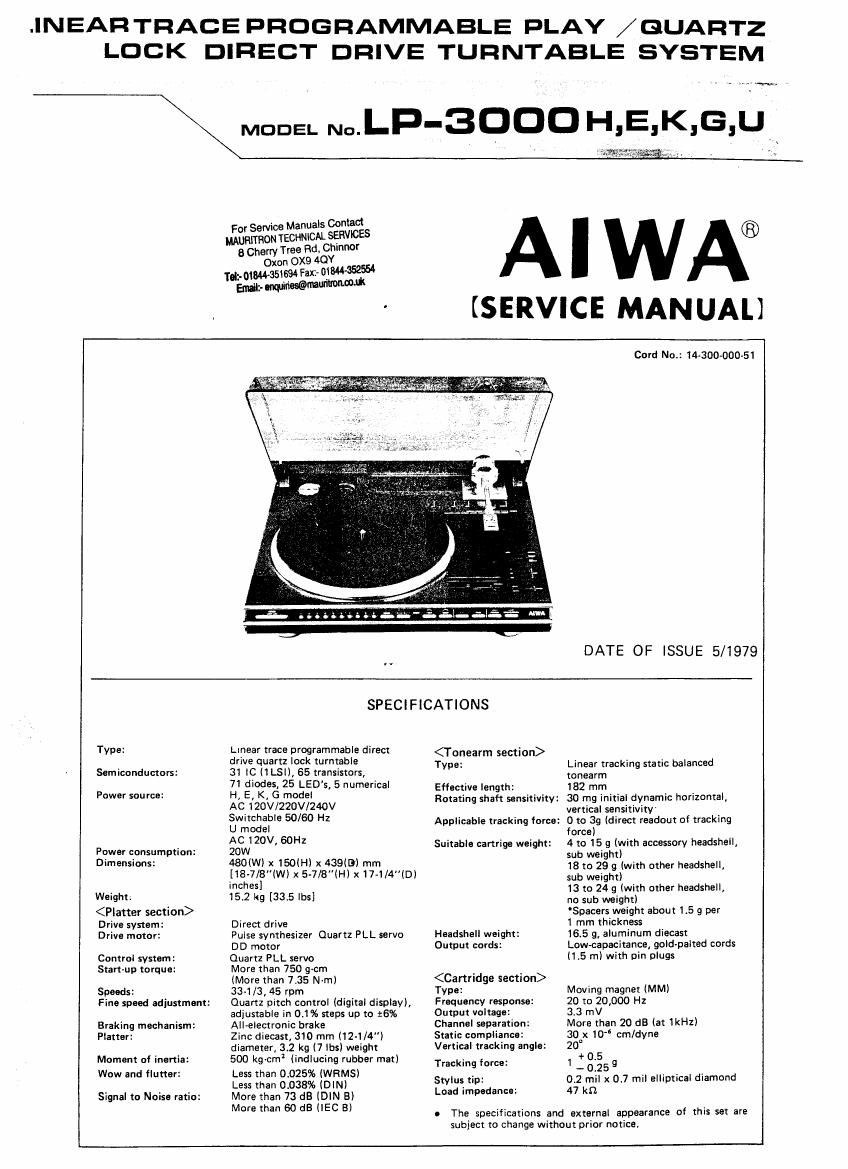
Aiwa LP 3000 Service Manual
This is the 35 pages manual for Aiwa LP 3000 Service Manual.
Read or download the pdf for free. If you want to contribute, please upload pdfs to audioservicemanuals.wetransfer.com.
Extracted text from Aiwa LP 3000 Service Manual (Ocr-read)
Page 1
.INEARTRACE PROGRAMMABLE PLAY /GUARTZ
LOCK DIRECT DRIVE TURNTABLE SYSTEM
v in...»
MODEL N°.LP-3OODH, E, K, G, u
For Service Manuals Contact
MAURITRON TECHNlOAL SEFNlCES
8 Cherry Tree Rd Chinnor
Oxon 0X9 940Y
m-mw- 35l694 Fax or
Enuilt- WWWW
mwalazdamg _
AIWA®
(SERVICE MANUAL
Card No.: 14300-000-51
DATE OF ISSUE 5/1979
Type:
Semiconductors:
Power source:
Power consumption:
Dimensions:
Weight:
Drive system:
Drive mater:
Control system:
Start-up torque:
Speeds:
Braking mechanism:
Platter:
Moment of inertia:
Wow and flutter:
Signal to Noise ratio:
Fine speed adjustment:
SPECIFICATIONS
Linear trace programmable direct
drive quartz lock turntable
31 (C (1LSI), 85 transistors,
71 diodes, 25 LED's, 5 numerical
H, E, K, G model
AC 120V/220V/240V
Switchable 50/60 Hz
U model
AC 120V, 60Hz
20W
480(Wl x 150(H) x 439(5) mm
[18-7/8"lW) x 5~718"lH)x17-1/4(Dl
inches]
15.2 kg [33.5 lbs]
Direct drive
Pulse synthesizer Quartz PLL servo
DD motor
Quartz PLL servo
More than 750 grcm
(More than 7.35 N-m)
33-1/3, 45 rpm
Quartz pitch control (digital display),
adjustable in 0.1% steps up to 16%
All-electronic brake
Zinc diecast, 310 mm (12-1/ ")
diameter, 3.2 kg (7 lbs) weight
500 kg-cn-il (indlucing rubber mat)
Less than 0.025% lWRMSl
Less than 0038% (DIN)
More than 73 dB (DIN B)
More than 60 dB ilEC Bl
Type:
Effective length:
Rotating shaft sensitivity:
Applicable tracking force:
Suitable cartrige weight:
Headshell weight:
Output cords:
Type:
Frequency response:
Output voltage:
Channel separation:
Static compliance:
Vertical tracking angle:
Tracking force:
Stylus tip:
Load impedance:
Linear tracking static balanced
tonearm
182 mm
30 mg initial dynamic horizontal,
vertical sensitivity
0 to 39 (direct readout of tracking
force)
4 to 15 g (with accessory headshell,
sub weightl
18 to 29 g (with other headshell,
sub weight)
13 to 24 g (with other headshell,
no sub weight)
Spacers weight about 1.5 g per
1 mm thickness
16.5 9, aluminum diecast
Low-capacitance, gold-palted cords
(1.5 m) with pin plugs
Moving magnet (MM)
20 to 20,000 H2
33 mV
More than 20 dB lat 1kHzl
30 x 10" cm/dyne
20°
+ 0 5
1 - 0.25 9
0 2 mil x 0.7 mil elliptical diamond
47 kfl
o The specifications and external appearance of this set are
subiect to change without prior notice,
Page 2
MODEL N0. LP-3000H,E,K,G,U AIWA
DISASSEMB LY INSTRUCTIONS
1. To Remove Top Panel 0 Mounting the Rear Panel
1) Anchor the rear panel and jack panel assembly loosely.
(Refer to Fig 4l
1) Remvoe 4 screws. (Refer to Fig.1)
Top panel screw
Top Danel screw
(Fig. 1>
2. To Remove Rear Panel 2) Tighten the top panel mounting screws. (Refer to Fig. 5)
1) Remove 4 screws (Refer to Fig. 2)
(Refer to Fig. 6)
2) Remove 5 screws (Refer to Fig. 3)
ék é ,
U@3" @34/2/
/uEe3-A "
(Fig. 3>
Note: When mounting and removing the rear panel, take care not
to bring the rear panel into Contact with the angle sensor
section.
If this section is touched, it will be thrown om of alignment
and this will require a re-adjustment of the angle sensorl
Page 15
AIWA
MODEL N0. LP-3000H,E,K,G,U
2-1-10 STT (sense leading trace) (Pin 14)
This signal is Low True and it enters this mode when the re-
cord edge and program intervals are detected,
During a program, the CPU sequentially counts and memorize:
these pulses and performs the operations
2-1-11 fi (sense position) (Pin 15)
This signal is a LOW pulse when the tonearm is in the rest
position, when it is at the edges (3) of the record sizes and at
the end (2) of the records It is a Low True signals
2-1-12 W (reset) (Pin 39)
When the power switch is turned on, this Low True signal re-
sets the CPU in a certain time period
2-1-13 MNL (manual)
This signal is always pulled up to HIGH because of the pro-
gram.
2-2 Interface system signals
The differences between the HIGH and LOW states of the
signals described under the CPU and its signals are omitted,
2-2-1 MKL (motor kill)
This is a High True signal which makes it impossible for the
linear trace motor to operate when in the HIGH state.
(LAZS-PI +- motor name)
22-2 W (motor up)
This is a Low True signal which causes the up/down tonearm
motor to raise the tonearm when it is in the LOW statet
(KCN'ZOBBA <- motor name)
2-2~3 MUTE (muting)
This is a High True signal which mutes the audio signals when
in the HIGH state,
2-2-4 W (motor down 1)
This is a Low True signal which causes the up/down tonearm
motor to lower the tonearm with a single turn of the record
with a 33 rpm record speed and which compensates for eccen-
tricity.
2-2-5 M-D-i (motor down 2)
This is a Low True signal which causes the uD/down tonearm
motor to lower the tonearm with a single turn of the record
with a 45 rpm record speed and which compensates for eccen-
tricity.
2-2-6 KMNL (flip-(lop manual)
This signal can be reversed (HIGH/LOW) every time the
KMNL ($19 MANUAL key) switch is depressed When this
switch is depressed when programmable, this Low True signal
can set the turntable to full auto (LOW state) onlyt
2-2-7 8?). (standard shell)
A standard headshell is defined as a headshell with the disc
sensor mounted, and this signal is LOW when this headshell is
attached, and HIGH when another headshell is attached With
a headshell with the disc sensor mounted, it can be set to SSH
with KMNL.
2-2»8 SW (sense mask 1)
SW (sense mask 2)
Film; (sense mask «3)
These three signals are used as digital bits and. together with
SPT, they form the record size and record end rest position
signal.
All these signals are Low True
3. Description of connector symbols
3-1 Power supply
The linear motor and the up/down motor rotate in both the
forward and reverse directions, the GND reference VDD and
VEE are used (or operation, and a voltage of VEE reference
VDD 24V is supplied for the phono motor operation.
15
3-2 CON 1 (connector 1)
3-2-1 SMDN (switch motor down)
The mode depends on the urn/down motor and tonearm, When
the tonearm is down, the SMDN Signal is LOW, and at all
other times it is HIGH.
3-2-2 SMUP (switch motor up)
The mode depends on the up/down motor and tonearm. When
the tonearm is up, the SMUP signal is LOW and at all other
times it is HIGH. The SMUP at the next pin is the reverse. The
levels are HIGH VDD and LOW GND,
3-2-3 A SNS (angle sensor)
This refers to the angle sensor which performs the linear track-
ing during record play, and a voltage proportionate to this
angle is fed out)
3-2-4 MSD (motor shield), DMT (down motor)
M50 is the shield wire of DMT (motor for tonearm raising and
lowering).
3-3 CON 2 (connector 2)
3-3-1 081 (disc sensor 1) DS 2 (disc sensor 2)
DS 1 output varies in accordance with the changes in the
light-reflecting obiectt The reference for the E and W)
signals is thereby provided, D5 2 is added to increase the
changes in Us 1 and there are no output variations.
3-3-2 LSD (left shield)
LS (left signal)
LE (left earth)
RE (right earth)
RS (right signal)
RSD (right shield)
3-4 CON 8, CON 9, CON 10, CON 11 (connectors 8, 9, 10, 11)
3-4-1 c_s (chip select) to through 8
CPU «1:, 1, 2 and 3 are BCD (binary r-r decimal) convened and
the input and output display relationship is controlled.
3-4.2 ETU (buffer) a) through 5
The program number, repeat and error displays are indicated
dynamically with m m and BTothrough m,
3-43 m through keyé
68-0 through E and m through TVS are combined in
matrix form, and all the rubber switches (except KSNS,
KMNL) are synchronized in their timing and controlled.
3-4-4 SNS UP (sensor up)
This refers to an increase in the level of the disc sensor, and the
sensitivity is improved W (key sensor 520) SWIIChES be-
tween normal sensitivity and increased sensitivity every time it
is depressed.
3-45 0-17, 5275, 6'37) . .. 0 (display)
m is synchronized with the W R, and the SIZE display
is operated statically with the combination of Kayo through
Key 1.
3-4-6 KMNL (key manual S19)
Every time this key is depressed, the output is reversed and
when SS-H is Low True, the programmable function can be
set on and off, in which case the CN12 PRG (program) and
NML (manual) lamps light up.