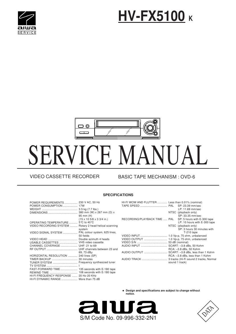
Aiwa HV FX5100 Service Manual

This is the 84 pages manual for Aiwa HV FX5100 Service Manual.
Read or download the pdf for free. If you want to contribute, please mail your pdfs to info@audioservicemanuals.com.

Page: 1 / 84
left right
Aiwa HV FX5100 Service Manual

Extracted text from Aiwa HV FX5100 Service Manual (Ocr-read)


Page 1

TABLE OF CONTENTS SPECIFICATIONS .............................................................................................................................................................. TABLE OF CONTENTS ..................................................................................................................................................... SERVICING NOTICES ON CHECKING ............................................................................................................................. IMPORTANT NOTICE ........................................................................................................................................................ DISASSEMBLY INSTRUCTIONS REMOVAL OF MECHANICAL PARTS AND P.C. BOARDS ........................................................................................... REMOVAL OF DECK PARTS .......................................................................................................................................... KEY TO ABBREVIATIONS ................................................................................................................................................. SERVICE MODE LIST ....................................................................................................................................................... PREVENTIVE CHECKS AND SERVICE INTERVALS ....................................................................................................... NOTE FOR THE REPLACING OF MEMORY IC ................................................................................................................ SERVICING FIXTURES AND TOOLS ................................................................................................................................ PREPARATION FOR SERVICING ..................................................................................................................................... VCR TEST TAPE INTERCHANGEABILITY TABLE ........................................................................................................... MECHANICAL ADJUSTMENTS CONFIRMATION AND ADJUSTMENT ............................................................................................................................ CONFIRMATION AND ADJUSTMENT OF TAPE RUNNING MECHANISM .................................................................. MECHANISM ADJUSTMENT PARTS LOCATION GUIDE ............................................................................................. ELECTRICAL ADJUSTMENTS BASIC ADJUSTMENTS ................................................................................................................................................... ELECTRICAL ADJUSTMENT PARTS LOCATION GUIDE ............................................................................................. TROUBLESHOOTING GUIDES .......................................................................................................................................... IC DESCRIPTIONS ............................................................................................................................................................ SERVO TIMING CHART .................................................................................................................................................... SYSTEM SWITCH MODE ................................................................................................................................................... SEMICONDUCTOR BASE CONNECTIONS ...................................................................................................................... BLOCK DIAGRAMS Y/C/AUDIO/HEAD AMP ................................................................................................................................................... SYSTEM CONTROL/SERVO/TIMER .............................................................................................................................. TUNER/HIFI/21PIN/OSD/VPS/NICAM ............................................................................................................................ OPERATION/POWER ..................................................................................................................................................... DECK SCHEMATIC DIAGRAM ........................................................................................................................................... OPERATION SCHEMATIC DIAGRAM ............................................................................................................................... PRINTED CIRCUIT BOARDS (OPERATION 1/2/DECK) ................................................................................................... PRINTED CIRCUIT BOARDS (SYSCON) .......................................................................................................................... Y/C/AUDIO/HEAD AMP SCHEMATIC DIAGRAM .............................................................................................................. SYSTEM CONTROL/SERVO/TIMER SCHEMATIC DIAGRAM ......................................................................................... 21PIN/OSD/VPS SCHEMATIC DIAGRAM ......................................................................................................................... TUNER/HIFI SCHEMATIC DIAGRAM ................................................................................................................................ POWER SCHEMATIC DIAGRAM ....................................................................................................................................... DISPLAY SCHEMATIC DIAGRAM ..................................................................................................................................... NICAM SCHEMATIC DIAGRAM ......................................................................................................................................... INTERCONNECTION DIAGRAM ........................................................................................................................................ WAVEFORMS .................................................................................................................................................................... MECHANICAL EXPLODED VIEW ...................................................................................................................................... MECHANICAL REPLACEMENT PARTS LIST ................................................................................................................... ACCESSORY REPLACEMENT PARTS LIST .................................................................................................................... CHASSIS EXPLODED VIEW (TOP VIEW) ......................................................................................................................... CHASSIS EXPLODED VIEW (BOTTOM VIEW) ................................................................................................................. CHASSIS REPLACEMENT PARTS LIST ........................................................................................................................... ELECTRICAL REPLACEMENT PARTS LIST .................................................................................................................... A-1 COVER A-1 A-2 A-2 B1-1 B2-1~B2-5 C1-1, C1-2 C2-1 C3-1, C3-2 C4-1 C5-1 C5-1 C6-1 D1-1, D1-2 D1-2, D1-3 D1-4 D2-1 D2-2 E-1~E-28 F-1, F-2 G-1 G-2 H-1 I-1 I-2 I-3 I-4 J-1 J-2 J-3 J-4~J-6 J-7 J-8 J-9 J-10 J-11 J-12 J-13 J-14 K-1 L1-1 L2-1 L2-1 M1-1 M1-2 M2-1 N-1~N-3

Page 2

SERVICING NOTICES ON CHECKING 1. KEEP THE NOTICES As for the places which need special attentions, they are indicated with the labels or seals on the cabinet, chassis and parts. Make sure to keep the indications and notices in the operation manual. 2. USE THE DESIGNATED PARTS The parts in this equipment have the specific characters of incombustibility and withstand voltage for safety. Therefore, the part which is replaced should be used the part which has the same character. Especially as to the important parts for safety which is indicated in the circuit diagram or the table of parts as a mark, the designated parts must be used. 3. PUT PARTS AND WIRES IN THE ORIGINAL POSITION AFTER ASSEMBLING OR WIRING There are parts which use the insulation material such as a tube or tape for safety, or which are assembled in the condition that these do not contact with the printed board. The inside wiring is designed not to get closer to the pyrogenic parts and high voltage parts. Therefore, put these parts in the original positions. PERFORM A SAFETY CHECK AFTER SERVICING 4. Confirm that the screws, parts and wiring which were removed in order to service are put in the original positions, or whether there are the portions which are deteriorated around the serviced places serviced or not. Check the insulation between the antenna terminal or external metal and the AC cord plug blades. And be sure the safety of that. IMPORTANT NOTICE The remote control for this model can be selected the Custom code 1 and Custom code 2. ¥ How to selection; Custom code 1 : P Custom code 2 :Press the Power key and 1 key on the remote control simultaneously for more than 2 seconds. Press the Power key and 2 key on the remote control simultaneously for more than 2 seconds. The Custom code 1 is only available for the VCR unit but the Custom code 2. When selected the Custom code 2 by mistake, just remove the batteries from the remote control for the moment or select the Custom code 1 as described above. A-2