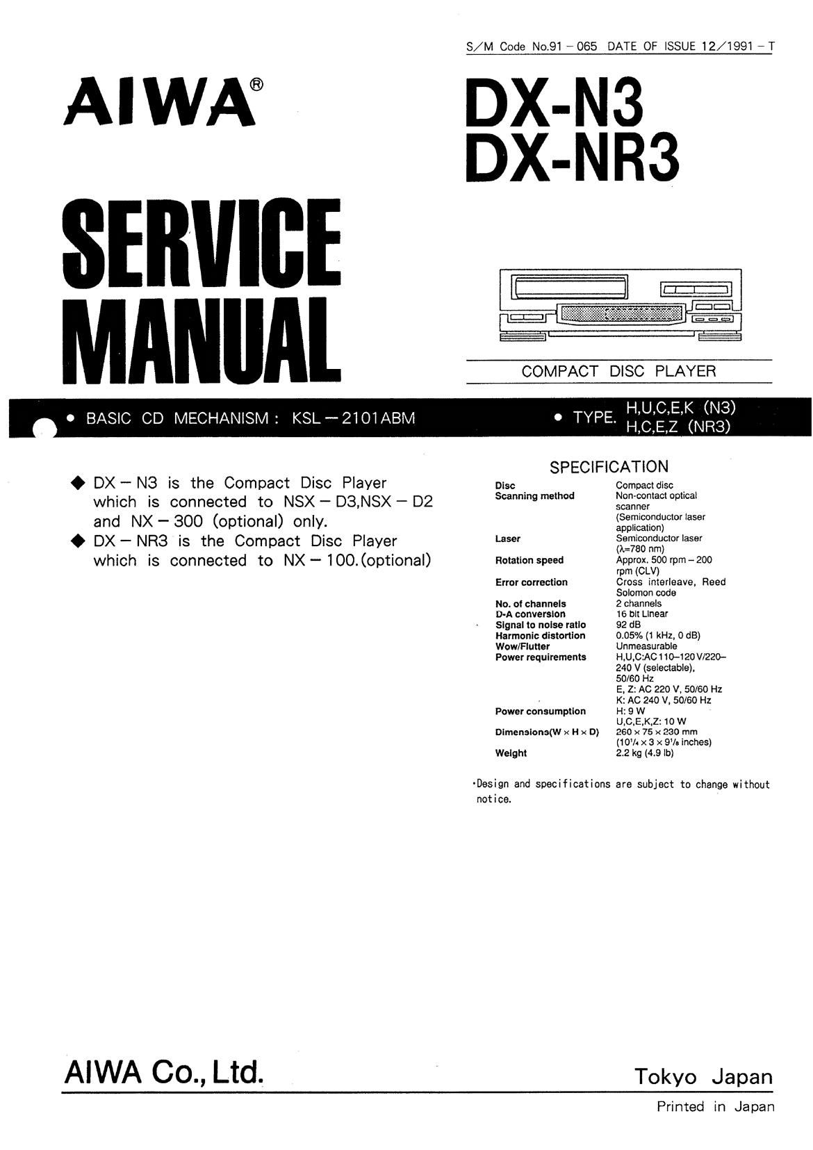
Aiwa DX NR3 Service Manual

This is the 25 pages manual for Aiwa DX NR3 Service Manual.
Read or download the pdf for free. If you want to contribute, please mail your pdfs to info@audioservicemanuals.com.

Page: 1 / 25
left right
Aiwa DX NR3 Service Manual

Extracted text from Aiwa DX NR3 Service Manual (Ocr-read)


Page 1

S/M Code No.91 -065 DATE OF ISSUE 12/1991 -T

AIWA® DX-

DX-
(21::
i
COMPACT DISC PLAYER

H,U,C,E,K (N3)
H,C,E,Z (NR3)

0 BASIC CD MECHANISM: KSL-2101ABM 0 TYPE.

SPECIFICATION

0 OX ~ N3 is the Compact Disc Player Disc . Compactdisc .
which is connected to NSX - 03,NSX - D2 539 mm §§:,;fi§?a°°p°a'
._ ' (Semiconductor laser
and NX $00 (optional) only. awn-canon)
0 OX - NR3 is the Compact DISC Piayer Laser 3613;532:5010! '859'
which is connected to NX - 100. (optional) Rotation speed ApprfgL390rpm~2oo
rpm
Error correction Cross interleave, Reed
Solomon code
No. ol channels 2 channels
D-A conversion 16 bit Linear
Signal to noise ratio 92 dB
Harmonic distortion 0.05% (1 kHz, 0 dB)
Wow/Flutter Unmeasurable
Power requirements H,U,C:AC 1 10-120 V/220-
240 V (selectable),
50/60 Hz

E. 2: AC 220 V. 50/60 Hz
, K: AC 240 V, 50/60 Hz
Power consumption H: 9 W
U,C.E.K,Z:1O W
Dimensions(w x H x D) 260 x 75 x 230 mm
(10% x 3 x 9'le inches)
Weight 2.2 kg (4.9 lb)

-Design and specifications are subject to change without
notice.

AIWA 00., Ltd. Tokyo Japan

Printed in Japan

Page 2

DISASSEMBLY INSTRUCTIONS

1. "Panel, Tray" and "CD Mechanism" Removal
(See Figure - 1.2)
1) Remove the Cabinet, Steel.
2) AFor AUTOMATIC operation
Press the OPEN/ CLOSE button to eject
the Tray".
AFor MANUAL operation (See Figure- 1)
Insert a flat-head screwdriver into the hole at
the direction of the arrow ® to eject the Tray.

3) Remove the Panel. Tray"
of the arrow.

in the direction

4) Remove 4 screws (®) and remove

the CD Mechanism".

Panel, Tray

Cabinet. Steel Fig - 1
I ACCESSORIES/ PACKAGE LIST
PART NO. REF.
CHANGED T0 N0. PART NO. DESCRIPTION
1 *81 -MDC- 905-019 INSTRUCTION BOOKLET EX
2 *87-034-773-010 CORD,PIN R-237W-1M
3 *81-MDB-951-019 REMOTE UNIT,RC-CN3 (NR3)
4 *87-032-845-019 PLUG,CONVERSION (H)
5 *81-MDC-951-019 CONNECTOR ASSY 2P CONT

(See Figure - 2)

(See Figure - 2)

CD Mechanism

COMMON
MODEL

92(-

X

Fig-2

Page 17

Pin No. Pin Name I/O Description
TMAX signal output terminal. HiZ in system clock.
TMAX cycle TMAX output
6 1 TMAX O Longer than specified cycle L
Shorter than specified cycle H(ZVREF)
Specified cycle HiZ
6 2 L P FN I LPF amplifier negative-phase input terminal for PLL.
6 3 L P F0 0 LPF amplifier output terminal for PLL.
6 4 V C O F I VCO filter terminal.
6 5 VC OX I External VCO clock input terminal.
6 6 P L C K O Playback data read clock output terminal.
6 7' MO D 0
6 8 MOD 1 I Internal operation mode setting input terminal.
6 9 MO D 2
7 0 WD CK 0 Word clock output terminal. Normally 88. 2 kHz.
7 1 CHCK 0 Channel clock output terminal. Normally 44.1 kHz.
7 2 B CK 0 Bit clock output terminal. Normally 1. 4112 MHz.
7 3 AOUT 0 Audio data output terminal.
7 4 C K S E I Internal clock selection terminal.
7 5 DOUT 0 Digital OUT output terminal.
7 6 71W I Test terminal. Normally "H or open.
7 7 TI? 0 High-speed monitor output terminal. High-speed mode when L.
7 8 EMP H O Emphasis ON/OFF indication signal output terminal. Emphasis ON when "H".
7 9 W I Test terminal. Normally "H" or open.
8 0 MCK 0 Master clock output terminal.

21

Page 18

lC.BU8559$

Pin No. Pin Name I/O Description

1 B Z I m (Not used.)

2 LED S 0 I 55 (Not used.)

3 L ED S 1 I m (Not used.)

4 L E D S 2 I m (Not used.)

5 LEDSS I mmot used.)

6 LEDS4 I m (Not used.)

7 L ED S 5 I m (Not used.)

8 L E D S 6 I m (Not used.)
9 'L E D s 7 I CTSIG'P

10 LEDCO I (Not used.)

1 1 L E D C I I (Not used.)

12 LEDCZ I (Not used.)

1 3 HA L T I H LT

1 4 O S C 2 I OSC terminal.

1 5 O S C 1 I OSC terminal.

1 6 GND - GND terminal.

1 7 AGND -- A-GND terminal.

1 8 AD I 0 I KEY input I.

1 9 CMP O I (Not used.)

2 0 CMP l I (Not used.)

2 1 ADI 1 I KEY input 2.
2 2 AVDD - Power supply terminal.

2 3 Tm I Reset terminal.

2 4 P I O 0 0 Analog switch A. (Not used.)
2 5 P I O 1 0 Analog switch B. (Not used.)
2 6 P I O 2 O MOTOR OPEN.
2 7 P I O 3 O ROTOR CLOSE.
2 8 P I 0 I IN SW.
2 9 P I 1 I OUT SW.

3 0 P I 2 I Remote input. (Not used.)
3 1 P I 3 I Remote input. (Not used.)
3 2 VDD - Power supply terminal.

22