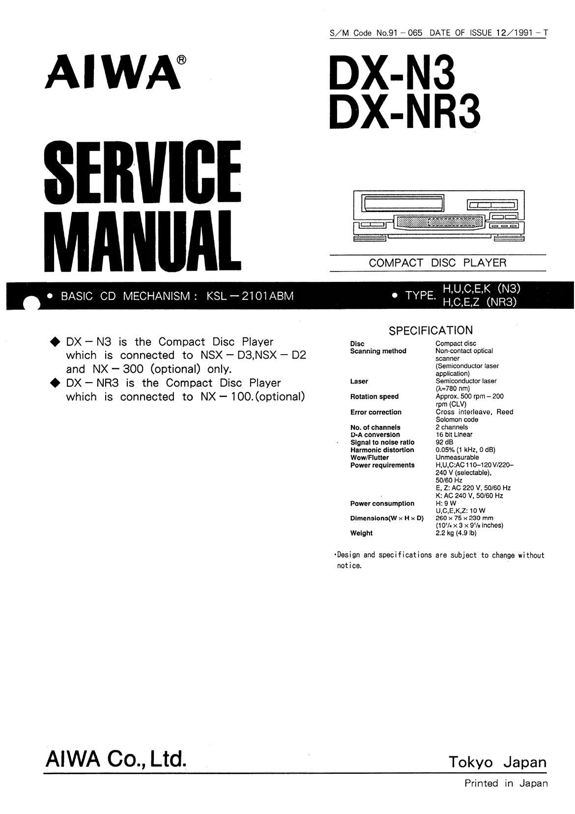
This is the 25 pages manual for Aiwa DX N3 Service Manual.
Read or download the pdf for free.
If you want to contribute, please mail your pdfs to info@audioservicemanuals.com.
S/M Code No.91 -065 DATE OF ISSUE 12/1991 -T
AIWA® DX-
DX-
(21::
i
COMPACT DISC PLAYER
H,U,C,E,K (N3)
H,C,E,Z (NR3)
0 BASIC CD MECHANISM: KSL-2101ABM 0 TYPE.
SPECIFICATION
0 OX ~ N3 is the Compact Disc Player Disc . Compactdisc .
which is connected to NSX - 03,NSX - D2 539 mm §§:,;fi§?a°°p°a'
._ ' (Semiconductor laser
and NX $00 (optional) only. awn-canon)
0 OX - NR3 is the Compact DISC Piayer Laser 3613;532:5010! '859'
which is connected to NX - 100. (optional) Rotation speed ApprfgL390rpm~2oo
rpm
Error correction Cross interleave, Reed
Solomon code
No. ol channels 2 channels
D-A conversion 16 bit Linear
Signal to noise ratio 92 dB
Harmonic distortion 0.05% (1 kHz, 0 dB)
Wow/Flutter Unmeasurable
Power requirements H,U,C:AC 1 10-120 V/220-
240 V (selectable),
50/60 Hz
E. 2: AC 220 V. 50/60 Hz
, K: AC 240 V, 50/60 Hz
Power consumption H: 9 W
U,C.E.K,Z:1O W
Dimensions(w x H x D) 260 x 75 x 230 mm
(10% x 3 x 9'le inches)
Weight 2.2 kg (4.9 lb)
-Design and specifications are subject to change without
notice.
AIWA 00., Ltd. Tokyo Japan
Printed in Japan
DISASSEMBLY INSTRUCTIONS
1. "Panel, Tray" and "CD Mechanism" Removal
(See Figure - 1.2)
1) Remove the Cabinet, Steel.
2) AFor AUTOMATIC operation
Press the OPEN/ CLOSE button to eject
the Tray".
AFor MANUAL operation (See Figure- 1)
Insert a flat-head screwdriver into the hole at
the direction of the arrow ® to eject the Tray.
3) Remove the Panel. Tray"
of the arrow.
in the direction
4) Remove 4 screws (®) and remove
the CD Mechanism".
Panel, Tray
Cabinet. Steel Fig - 1
I ACCESSORIES/ PACKAGE LIST
PART NO. REF.
CHANGED T0 N0. PART NO. DESCRIPTION
1 *81 -MDC- 905-019 INSTRUCTION BOOKLET EX
2 *87-034-773-010 CORD,PIN R-237W-1M
3 *81-MDB-951-019 REMOTE UNIT,RC-CN3 (NR3)
4 *87-032-845-019 PLUG,CONVERSION (H)
5 *81-MDC-951-019 CONNECTOR ASSY 2P CONT
(See Figure - 2)
(See Figure - 2)
CD Mechanism
COMMON
MODEL
92(-
X
Fig-2
lC.BU8559$
Pin No. Pin Name I/O Description
1 B Z I m (Not used.)
2 LED S 0 I 55 (Not used.)
3 L ED S 1 I m (Not used.)
4 L E D S 2 I m (Not used.)
5 LEDSS I mmot used.)
6 LEDS4 I m (Not used.)
7 L ED S 5 I m (Not used.)
8 L E D S 6 I m (Not used.)
9 'L E D s 7 I CTSIG'P
10 LEDCO I (Not used.)
1 1 L E D C I I (Not used.)
12 LEDCZ I (Not used.)
1 3 HA L T I H LT
1 4 O S C 2 I OSC terminal.
1 5 O S C 1 I OSC terminal.
1 6 GND - GND terminal.
1 7 AGND -- A-GND terminal.
1 8 AD I 0 I KEY input I.
1 9 CMP O I (Not used.)
2 0 CMP l I (Not used.)
2 1 ADI 1 I KEY input 2.
2 2 AVDD - Power supply terminal.
2 3 Tm I Reset terminal.
2 4 P I O 0 0 Analog switch A. (Not used.)
2 5 P I O 1 0 Analog switch B. (Not used.)
2 6 P I O 2 O MOTOR OPEN.
2 7 P I O 3 O ROTOR CLOSE.
2 8 P I 0 I IN SW.
2 9 P I 1 I OUT SW.
3 0 P I 2 I Remote input. (Not used.)
3 1 P I 3 I Remote input. (Not used.)
3 2 VDD - Power supply terminal.
22
Pin No. Pin Name I/O Description
4 6 W I Not used. (PU-R)
4 7 WSE-T I CD board reset detection.
4 8 R E C I Not used. (6ND) v
4 9 S Y N C I Not used. (PU-R)
5 0 T U - C E I Not used. (PU-R)
5 1 RX P - C ONT I Not used. (GND)
5 2 R 7 3 I/O Not used.
5 3 S E G 0
S . S 0 Not used.
6 3 S E G 1 0
6 4 S E G 1 1
S S 0 LCD driver segment output.
7 5 S E G 2 2
7 6 S E G 2 3
S S 0 Not used.
7 7 S E G 2 4
7 8 S E G 2 5
S S 0 LCD driver segment output.
8 0 S E G 2 7
24