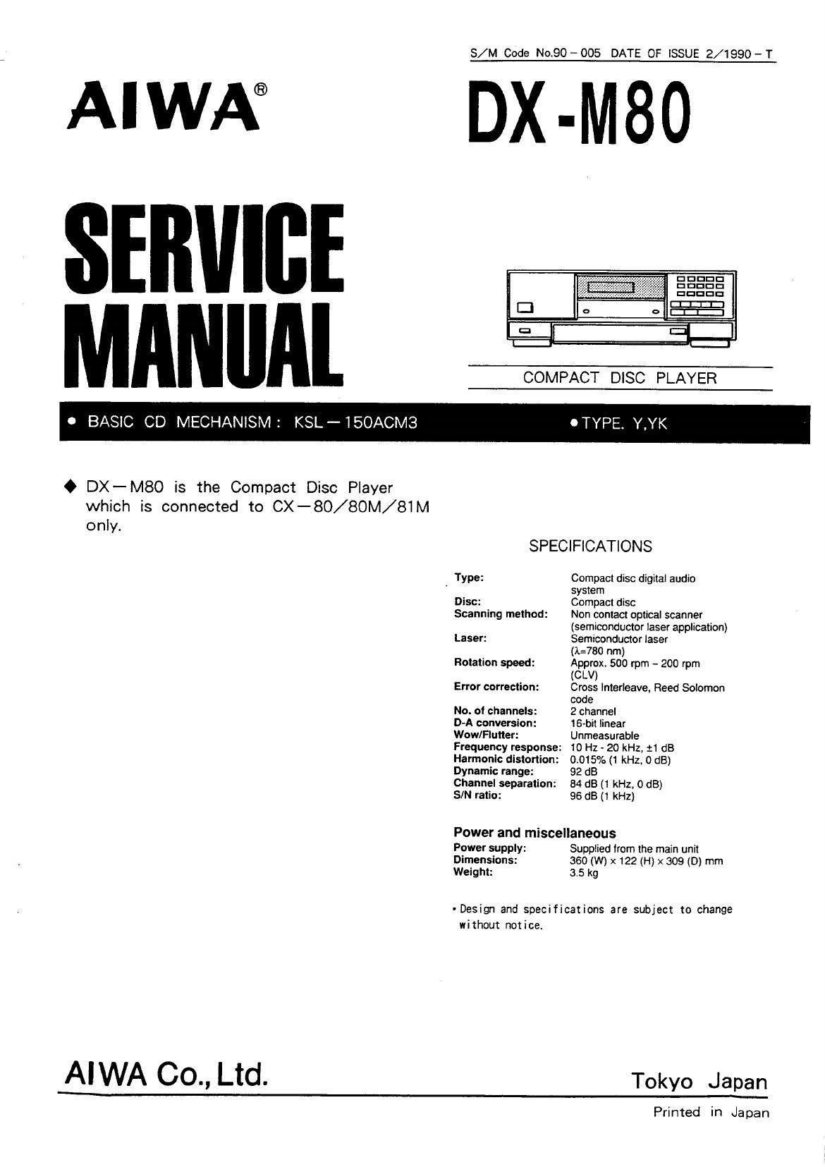
Aiwa DX M80 Service Manual

This is the 20 pages manual for Aiwa DX M80 Service Manual.
Read or download the pdf for free. If you want to contribute, please mail your pdfs to info@audioservicemanuals.com.

Page: 1 / 20
left right
Aiwa DX M80 Service Manual

Extracted text from Aiwa DX M80 Service Manual (Ocr-read)


Page 1

S/M Code No.90 - 005 DATE OF ISSUE 2/1990 - T

AIWA® DX-M

MAN"Al COMPACT DISC PLAYER

0 BASIC CD MECHANISM: KSL~15OACM3 OTYPE. Y,YK

O DX-MBO is the Compact Disc Player
which is connected to CX-80/8OM/81M

o n ly.
SPECIFICATIONS
Type: Compact disc digital audio
' system

Disc: Compact disc

Scanning method: Non contact optical scanner
(semiconductor laser application)

Laser: Semiconductor laser
0:780 nm)

Rotation speed: Approx. 500 rpm - 200 rpm
(CLV)

Error correction: Cross interleave, Reed Solomon
code

No. of channels: 2 channel

D-A conversion: 16-bit linear

Wow/Flutter: Unmeasurable

Frequency response: 10 Hz - 20 kHz, :1 dB
Harmonic distortion: 0.015% (1 kHz. 0 dB)

Dynamic range: 92 dB
Channel separation: 84 dB (1 kHz, 0 dB)
SIN ratio: 96 dB (1 kHz)

Power and miscellaneous

Power supply: Supplied from the main unit
Dimensions: 360 (W) x 122 (H) x 309 (D) mm
Weight: 3.5 kg

- Design and specifications are subject to change
without notice.

AIWA 00., Ltd. Tokyo Japan

Printed in Japan

Page 2

CAUTIONS WHEN SERVICING

The DX-MBO has no power supply circuit. Power should be supplied from (IX-80. (EX-BUM. (IX-81M using an ll-core
flat cable. During repair, connect DX-M80 to the CX-80, CX-BOM, CX-81M to supply the power.
When there is no [IX-80, (IX-80M, (IX-81M, supply the power in the manner below.

(When repairing without CX-SO, CX-80M, CX-81M)
1. Remove soldering from C2) and © terminals of T51 not to
flow DC through T51.

2. Connect the Multi-Power Supply(LPS-9088) in the manner below.

. FL501 does not light. as AC power for FLSOl is not supplied.

The voltages below are supplied to each CONlOl
terminal the external Dower source.

A MA I N C . B
. "G -> Lch our
PUT{W:: 6" <2) -
h® A ch our
{Remove soldering. 5ND ® GND
®
©
G)
AC-COM @ GND
AC-l ¢--13v
AC-Z ® ~--+I3v

3. Multi-Power (LPS-9088) Connection

Connect to .ll of the LPS-9088 using a multi-conversion harness.

Conversion harness connect ion

l | : Short bar
2 2 *--> : Jumper cable
3 3 " --> : Pin olug's ground cable
4 4 0 :Power output terminal
5 5 © :Relay terminal
4480. 6 e -> Multi-Power Supply © :Pin jack
7 7
6 8
9 9
IO I0 External unit External unit
H H (Amplifier. etc.) (Sourse)
l2
I3 INPUT

mm! a °®© O©©©
:®®®® ©6©©

Page 13

Pin No. Pin Name I/O Description

3 5 K E Y 1

3 6 K E Y 2

3 7 K BY 3 l KEY input.

3 8 K E Y 4

3 9 K E Y 5

4 U E O P - 0 F F - Connected to GND.

4 1 NC - Reserved.

4 2 SYNC I/O Sync. signal to other components input or output. (8-bit serial)

4 3 NC -- Reserved.

4 4 SQCK Sub-code 0 read and clock input.

4 5 GF S l Display signal input for frame sync. lock status.

4 6 S U B Q Sub-code 0 input.

4 7 MUTG O Muting output to DSP.

4 8 S ENS 1 Connected to DSP SENS terminal.

4 9 W 0 System reset output.

5 0 DATA 0 Serial data output to DSP.

5 l XLT Data latch output.

5 2 C L K Data transmission clock.

5 3 OP E N 0 Tray open output. High when opening.

5 4 C L O S E Tray close output. High when closing.

5 5 W Tray open detection switch. Low when the tray is open.

5 6 m Tray open detection switch. Low when the tray is closed.

5 7 FOK 1 Indicates the status of focus. High when in focus.

5 B P - S MOD E P -S 1 mode: High when peak search is performed every recording.
P - S 2 mode: Low when If the disc has not been changed and the program

has not been revised, only the peak point is played back.

5 9 m 0 Laser diode 0N/0FF output. Low when the laser diode is on.

6 0 P -O F F 0 System ON/OFF output. High when power is off.

6 l P-C ONT 1 System ON/DFF output from other components.

6 2 RMC l 42-bit serial remote control input.

6 3 NC - Reserved.

6 4 RANDOM indicates random play operation. High in random mode. (Reserved)

6 5 m 0 Holds the peak of input signal from other components in the peak Search
mode. High when peak search mode.

6 6 m Initial signal and AD START pulse output to the A/D conversion circuit.

6 7 W Timing signal input for A/D conversion.

6 8 m Random switch input. Low during random play and timer random play.

6 9 W I Timer play mode switch input. Low in timer play mode.

7 0 WW Power switch input. ou/orr (STAND BY) is switched.

7 1 GND - Connected to GND.

7 2 NC - Reserved.

7 3 NC - Reserved.

7 4 WDCK 1 Reference clock input for the peak search (AD conversion circuit)

7 5 VRE F - Connected to 48.

17