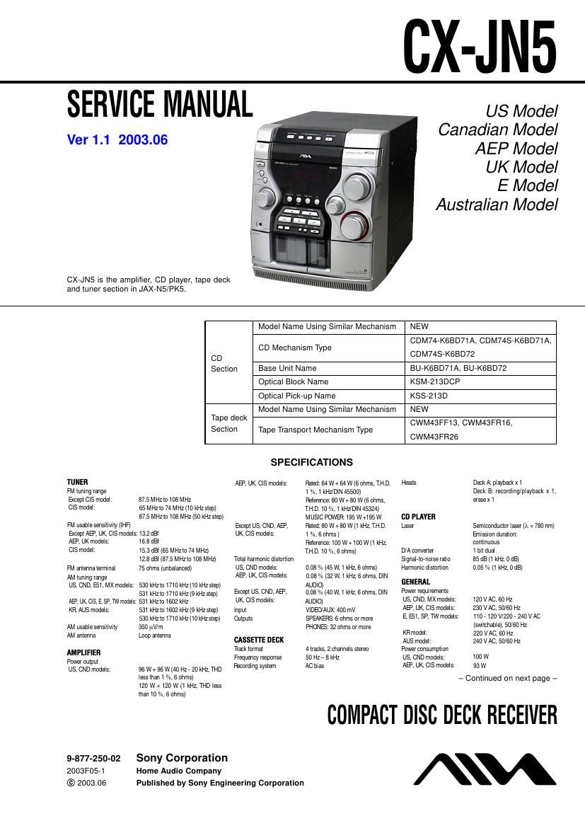
Aiwa cx jn5

This is the 78 pages manual for aiwa cx jn5.
Read or download the pdf for free. If you want to contribute, please mail your pdfs to info@audioservicemanuals.com.

Page: 1 / 78
left right
aiwa cx jn5

Extracted text from aiwa cx jn5 (Ocr-read)


Page 2

CX-J N5

Except US, CND, AEP, UK,
CIS models: 105 W
Power consumption With ECO mode on 0 25 W
In standby mode With ECO mode all 20 W
Dimensions (WxHx D) 280x330x3825 mm
(111/23 x13 x 15 1/2 in.)

Weight

US, CND. B1, KR models: 8.0 kg (17 lbs 10 oz)
AEP UK models: 7 2kg

CIS model: 7 6kg

E MX, SP, TW modeis: 7,9 kg

Specifications and external appearance are subject to change
Without notice.

Abbreviation

AUS :Austrailan model

CND :Canadian model

E51 : Chilean and Peruvian models

TW : Talmn model

COPYRIGHT
Check copyright laws relevant to recordings Irorn dISCS, tuner
or tape lor the country where the unit is to be used.

Licensed by BBE Sound, Inc. under USP4638258, 5510752
and 5736897.

SAFETY CHECK-OUT

After correcting the original service problem, perform the followA
ing safety check before releasing the set to the customer:

Check the antenna terminals, metal trim, metallized knobs,
screws, and all other exposed metal parts for AC leakage.

Check leakage as described below.

LEAKAGE TEST

The AC leakage from any exposed metal part to earth ground and

from all exposed metal parts to any exposed metal part having a

return to cha , must not exceed 0.5 mA (500 microamperes.).

Leakage current can be measured by any one of three methods.

1. A commercial leakage tester, such as the Simpson 229 or RCA
WTA540A. Follow the manufacturers instructions to use these
instruments.

2. A battery~operated AC milliammeter. The Data Precision 245
digital multimeter is suitable for this job.

3. Measuring the voltage drop across a re. ' 'tor by means of a
VOM or batteronperated AC voltmeter. The limit indica~
tion is 0.75 V, so analog meters must have an accurate low-
voltage scale. The Simpson 250 and Sanwa SH-63Trd are ex-
amples of a passive VOM that is suitable. Nearly all battery
operated digital multimeters that have a 2 V AC range are suit-
able. (See Fig.A)

CAUTION

Use of controls or adjustments or performance of procedures
other than those specified herein may result in hazardous ra-
diation exposure.

This appliance is classified as
a CLASS I LASER product.
The CLASS 1 LASER
PRODUCT MARKING is
located on the rear exterior.

The following caution label is located inside the unit.

CAUTION , INVISIBLE LASER RADIATION WHEN OPEN AND
INTERLOCKS DEFEATED avom Exposuns TO BEAM
ADVARSEL : ustLiG LASERSTRALING VED ABNING NAR
SIKKERHEDSAFBRVDERE ER unE AF summon unocA uosAETTEtsz
ran smstms

VORSICHT UNSICHYBARE LASERSTRAHLUNG WENN
ABDECKUNG 550mm um: sicnznzirsvzamssstune
UEERERDCKT NICHT DEM STRAHL AUSSETZEN

: AVATTAESSAJA SUOJALUKIYUS OHIYETTAESSA DIET ALL

VARO!
TIINA NAKYMATTOMALLE LASERSAYEILVLLE ALA KATSO SATEESEEN

VA R N | N G : OstLiNG LASERSTHALING NAR DENNA DELAR OPPNAD
ocH SPARREN AR URKOPPLAD BETRAKM EJ STRALEN

ADVE RSEL , USYNLIG LAsERsTRAtiNG NAR oEKsEt APNES 06
SIKKERHEDSLAS BRYTES UNNGA EKSPONERING row STRALEN

VI GYAZAT! : A EURKOLAT NYITASAKOR LATHATATLAN LEzEasur
GARVESZELY KERULJE A BESUGARZAST

DANGER DANGER

INVISIBLE LASER RADIATION DE LESER
RADIATION WHEN OPEN INVISIBLE LORS D'OUVERTURE.
AND INTERLOCK AVEC L'ENCLENCHEMENT DE
DEFEATED. AVOID SECURITE ANNULE. EVITER
DIRECT EXPOSURE TO L'EXPOSITION DIRECTE .AU
BEAM. RAYON.

SAFETY-RELATED COMPONENT WARNING

COMPONENTS IDENTIFIED BY MARK A OR DOTTED
LINE WITH MARK A ON THE SCHEMATIC DIAGRAMS
AND IN THE PARTS LIST ARE CRITICAL TO SAFE
OPERATION. REPLACE THESE COMPONENTS WITH
SONY PARTS WHOSE PART NUMBERS APPEAR AS
SHOWN IN THIS MANUAL OR IN SUPPLEMENTS PUB-
LISHED BY SONY.

To Exposed Metal
Parts on Set

AC
/ voltmeter
(0. 75 V)

_T_ Eaflh Ground
Fig. A. Using an AC voltmeter to check AC leakage.

Notes on chip component replacement

Never reuse a disconnected chip component.
Notice that the minus side of a tantalum capacitor may be dam~
aged by heat.

Flexible Circuit Board Repairing

Keep the temperature of the soldering iron around 270 C dur-
ing repairing.

Do not touch the soldering iron on the same conductor of the
circuit board (within 3 times).

Be careful not to apply force on the conductor when soldering
or unsoldering.

ATTENTION Au COMPOSANT AYANT RAPPORT
A LA sEcuanE!

LEs COMPOSANTS IDENTIFIES PAR UNE MARQUE A
sun LEs DIAGRAMMES SCHEMATIQUES ET LA LISTE
DES PIECES SONT CRITIQUES POUR LA sEcuanE
DE FONCTIONNEMENT. NE REMPLACER CES COM-
POSANTS QUE PAFI DEs PIECES SONY DONT LEs
NUMEROS SONT DONNEs DANS CE MANUEL ou
DANS LEs SUPPLEMENTS PUBLIES PAR SONY.