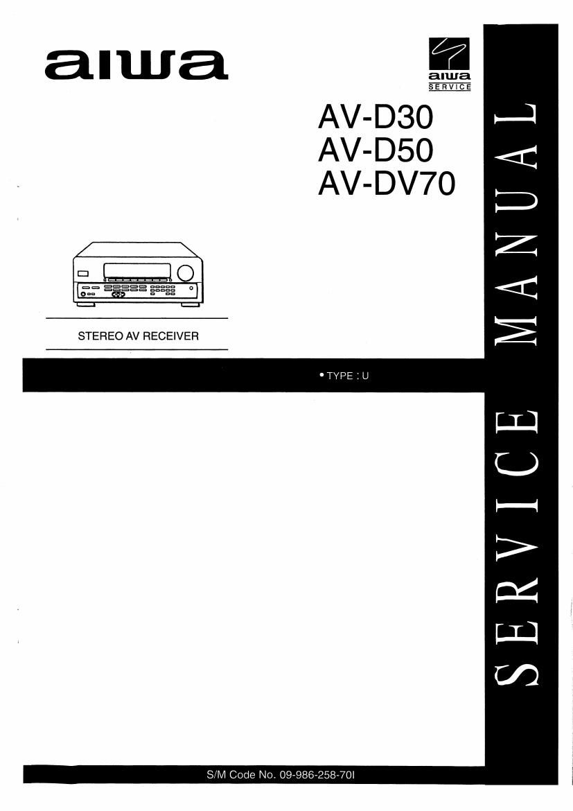
Aiwa AV D50 Service Manual

This is the 32 pages manual for Aiwa AV D50 Service Manual.
Read or download the pdf for free. If you want to contribute, please mail your pdfs to info@audioservicemanuals.com.

Page: 1 / 32
left right
Aiwa AV D50 Service Manual

Extracted text from Aiwa AV D50 Service Manual (Ocr-read)


Page 2

SPECIFICATIONS [AV-D30]

FM tuner section

Tuning range

Usable sensitivity
(IHF)

Antenna terminals

87.5 MHz to 108 MHZ
13.2 dBI I

75 ohms (unbalanced)

AM tuner section

Tuning range

Usable sensltlvlty
Antenna

530 kHz to 1710 kHz (10 kHz step).
531 kHz to 1602 kHz (9 kHz step)
350 pV/m

Loop antenna

Amplifier section

Power output

Total harmonic
distortion
Inputs

Outputs

Muting

[Stereo Mode]

Front

85 watts per channel. Min. RMS at 5
ohms, (ram 40 Hz to 20 kHz. with no
more than 0.9% Tolal Harmonic
Distortion

[Dolby Pro Logic or 5.1 CH Mode]
Front

70 watts per channelI Min. HMS at 5
ohms, from 40 Hz to 20 kHz. with no
more than 0.9% Total Harmonic
Distortion

Rear (Surround)

35 watts per channel, Min. HMS ate
ohms. 1 kHz. with no more than 0.9%
Total Harmonic Distortion

Center

70 watts, Min. RMS at 8 ohms, 1 kHz.
with no more than 0.9% Total
Harmonic Distortion

0.08 % (50 W. 1 kHz, 6 ohms, Front)

AUDIO IN
PHONO: 2.5 mV. adjustable (47
kohms)
CD: 250 mV, adjustable (47
kohms)
TAPE MONITOR: 250 mV (47
kohms)
VIDEO IIDVD/MD, VIDEO 2/LD/
TV, VIDEO 3, AUX: 250 mV,
adjustable (47 kohms)
5.1 INPUT (FRONT. SURROUND.
CENTER. SUB-WOOFER): 400
mV (47 kohms)
VIDEO IN: 1 Vp-p (75 ohms)
AUDIO OUT (REC OUT): 200 mV (1
kohm)
VIDEO OUT (MONITOR): 1 Vp-p (75
ohms)
SUPER WOOFER: 200 mV
FRONT SPEAKERS IMP: 8!)
(front speakers A and B): accepts
speakers of 8 ohms or more.
SURROUND SPEAKERS IMP: 8(2
(surround speakers): accepts
speakers oi 8 ohms or more
CENTER SPEAKER IMP: Bl): accepts
a speaker ol 8 ohms or more
PHONES (stereo jack): accepts
headphones oi 32 ohms or more
~20 dB

General

Power requirements 120 V AC, 60 Hz
Power consumption 125 W

Dimensions 430 x 155 x 351 mm
(WxHxD) (17x6la xtala in,)
Weight 10.0 kg (22 lot 021)

0 Design and specifications are subject to change without notice

I Manulacturad under license from Dolby Laboratories Licensing
Corporalion.

O DOLEY, the double-D symbol DC are PRO LOGIC are
trademarks of Dolby Laboratories Licensing Corporation.

Page 26

Pin No. Pin Name I/O Description
42 m I Power failure detected input L" to stop clock and hold memory
43 RE-VOL I Rotary encoder signal input
44 RDS-SIG I Tuner signal input
45 MIC I Microphone input for auto VF display
46 KEY3 I
47 KEYZ I Key input (AID)
48 KEYI I
49 SYNC DET I SYNC detector input for OSD
50 AVSS - GND
51 LED CD 0 CD LED ON/fi output
52 LED-VIDEOl O VlDEOl LED ONIW output
53 LED-VIDEOZ 0 VIDEOZ LED ON/aFF output
54 LED-VIDEO3 0 VIDEOS LED ON/O-FF output
55 P35 0 FL segement P35 output
56 P34 0 FL segement P34 output
57 P33 0 FL segement P33 output
58 P32 0 FL segement P32 output
59 P31 0 FL segement P31 output
60 P30 I/O FL segement P30 output/LW mode data input to diode
61 P29 I/O FL segement P29 output/FMI (OIRT) data input to diode
62 P28 I/O FL segement P28 output/RDS data input to diode
63 P27 110 FL segement P27 output/BEE data input to diode
64 P26 I/O FL segement P26 output/AM stereo, wide band data input to diode
65 P25 I/O FL segement P25 output/intial AM 10 kHz step data input to diode
66 P24 I/O FL segement P24 output/VF. KEY CON, ECHO data input to diode
67 P23 110 FL segement P23 output/OSD data input to diode
68 P22 I/O FL segemem P22 output/DOLBY digital (AC3) data input to diode
69 P21 0 FL segement P21 output
70 P20 0 FL segement P20 output
71 P19 0 FL segement P19 output
72 P18 0 FL segement P18 output
73 P17 0 FL segement P17 output
74 P16 I/O FL segement P16 output/tuner stereo detected input
75 P15 I/O FL segement P15 output/headphone mute detected input
76 P14 1/0 FL segement P14 output/reference clock input for timer watch
77 P13 0 FL segement P13 output
78 P12 0 FL segement P12 output
79 VDD2 - Power supply input
80 VFL - Power supply input for FL display
81 P11 0 FL segement P11 output
82 P10 0 FL segement P10 output

40