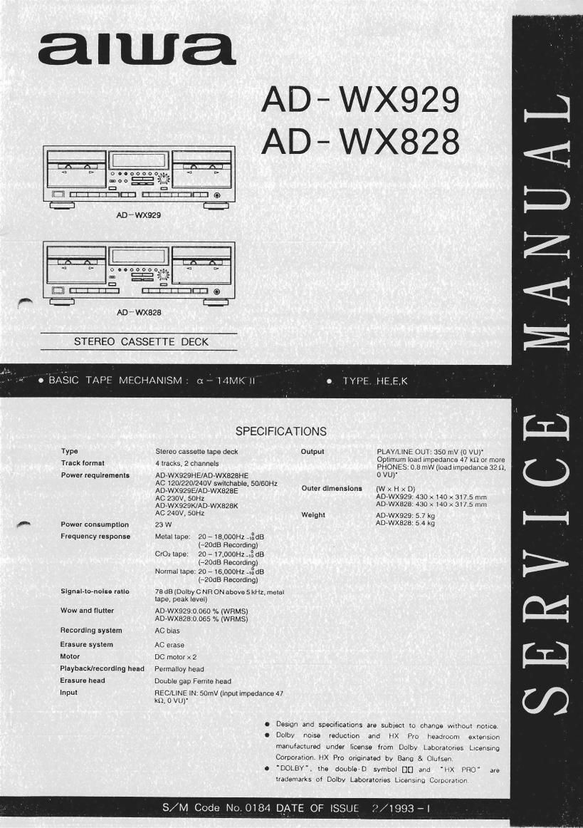
Aiwa AD WX828 Service Manual

This is the 31 pages manual for Aiwa AD WX828 Service Manual.
Read or download the pdf for free. If you want to contribute, please mail your pdfs to info@audioservicemanuals.com.

Page: 1 / 31
left right
Aiwa AD WX828 Service Manual

Extracted text from Aiwa AD WX828 Service Manual (Ocr-read)


Page 2

w... -mr- .-A.. . . ,...-.n.. .Wlpq-wg-m. M. w

-. w. u-Wmmvm-

,m-..,_.,_-,, w; .

CAUTION WHEN SERVICING

If the tape transport mechanisms are in the following state, an abnormal
sound may be heard when the power switch is turned on and the mechanisms
may not operate. In this case, turn the power switch off and then on again.
The mechanisms will operate normally.(The microprocessor will be reset.)

Case :The PLAY solenoids in both decks l and decks 2 have drifted down
from the normal positions and also the FR solenoid in one deck
has drifted down from the normal position.

Case :The FR solenoids in both decks 1 and decks 2 have drifted down
from the normal positions and also the PLAY solenoid in one deck
has drifted down from the normal position.

TRANSISTOR ILLUSTRATION

S G D B C E B C E E C B
2SK373 DTA143 2881330 25A933
DTC1 14 2831370 2SA952
DTCIA4 28A1296
ZSC945
28C1740
ZSC1815
28C2001
2802240
230655
IACCESSORIES/PACKAGE LIST
PART NO. REF.
CHANGED T O N 0. PART NO. DESCRIPTION
*BZ-Dll-QOI-OIS IB£K(S)

*82-0'1-030-019
*87-034-738-019
*67-042-062-019

uuw-

K) - W101 (AD - WX929)
OORD PIN 189 - 0760
PLUG ADPTR S - I6115

COM MON
MODEL

QTY

_._.....

Page 19

Pin No. Pin Name l/O Description
33 P20 0
34 P19 0
35 P18 0
36 P17 0 Segment outputs to drive the FL display. Lights at "H.
37 P16 0 P17-P20 are also used to scan the operation mode during initialization.
38 P15 0
39 P14 0
40 P13 0
41 VDDVPP 7 Power supply of FL display drive outputs. Connected to 5V.
42 VP * Negative power supply for pullrdown resistors. 727V is connected.
43 F12 O
44 F11 O
45 P10 0
46 P9 0
47 P8 0
48 P7 0 Segment outputs to drive the FL display. Lights at H".
49 Fe O P2'P12 are also used as the SW scan and AD scan outputs.
50 P5 0
51 P4 0
52 P3 0
53 P2 0
54 P1 0
55 NC -
Not used.
56 NC ~
57 DTO 1
SW scan inputs.
58 UPI I
59 I 7 QUICKI I
Quick sensor inputs.
60 I - QUICKZ l
61 O 7 SOL - PLZ O
62 0" SOL ' FRZ O Outputs to control the plunger driver in the mechanism.
63 O- SOL . PM 0 The plunger is attracted at H.
64 O - SOL - FRl O

Note : The initial output of P6 and P61 -P84 are set to L" and others to H" when reset.

28